Building a DIY Sourdough Proofer (Dough133)
Posted on March 5, 2024 • 14 min read • 2,776 words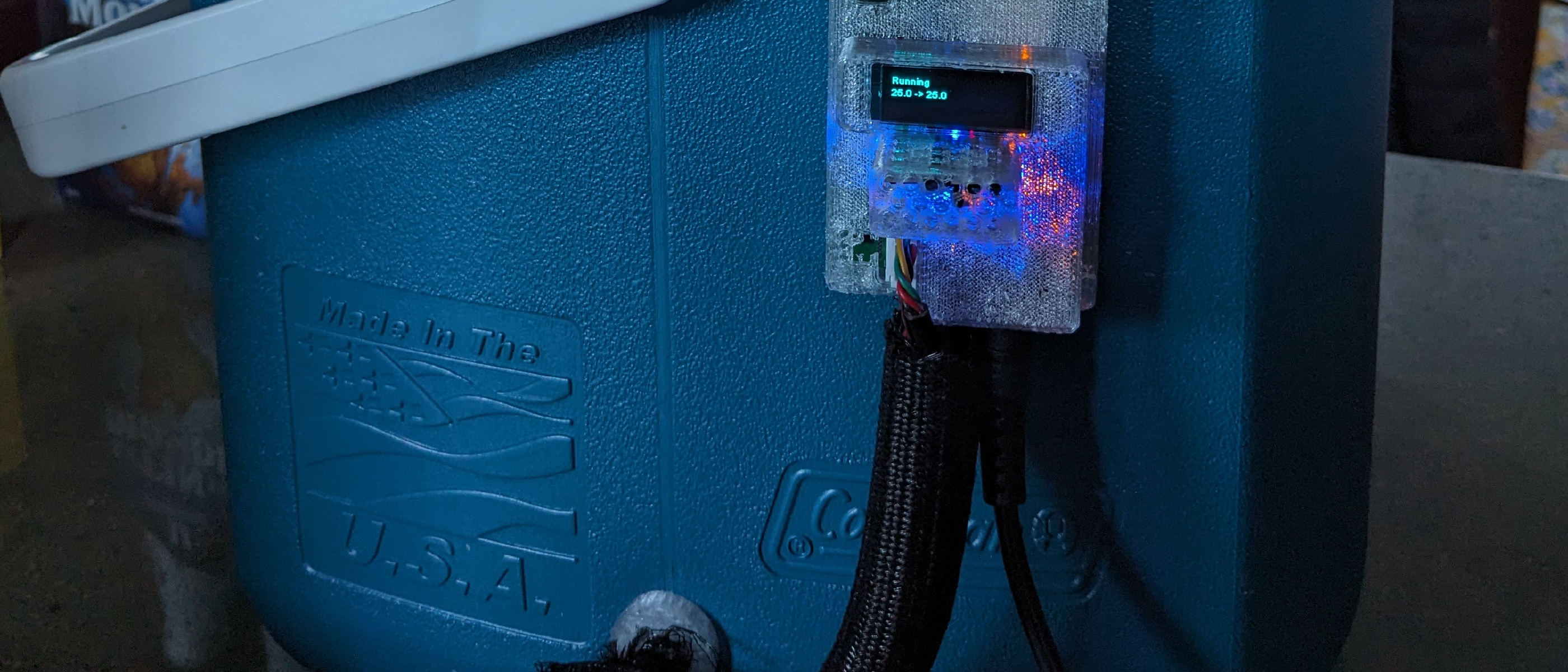
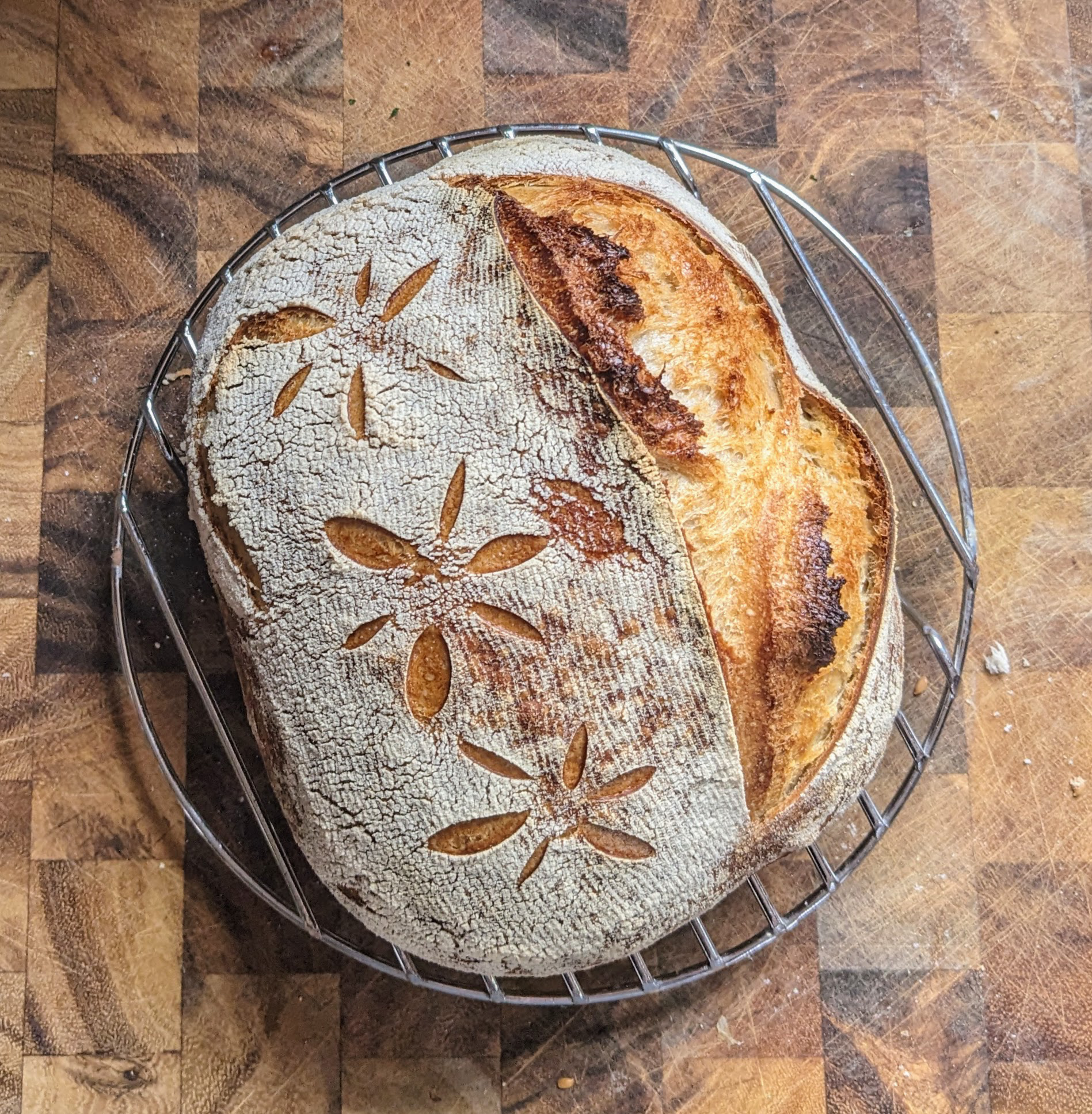
Our family started making sourdough bread during the pandemic, but our kitchen is usually too cold for the dough. So I built an intelligent heated enclosure for fermenting and proofing sourdough.
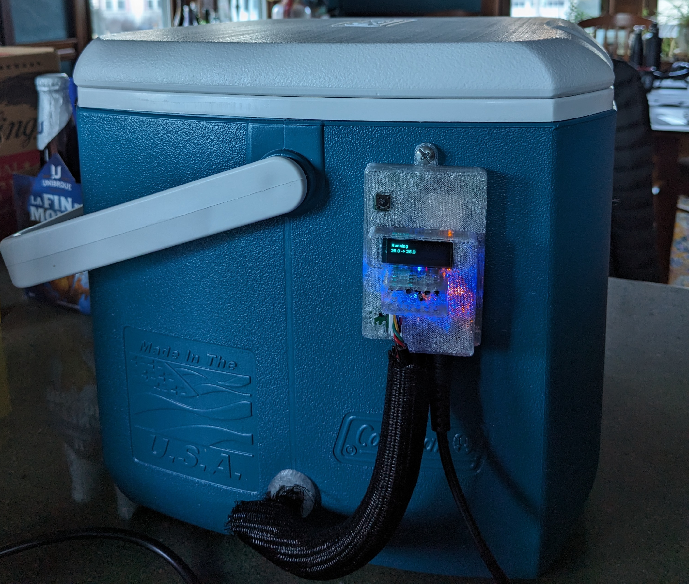
I call my system “Dough133.” It is pronounced “Dough Lee”, but with a 1337 accent and optional touch of irony. It uses a small cooler as the container for the dough, a PTC heater, a simple temperature/humidity sensor in the cooler to monitor conditions, and my own microcontroller board mounted on the outside of the cooler for control.
I’m happy with the result. The enclosure quickly reaches the goal temperature, it tracks the target temperature extremely precisely, it integrates nicely with our home automation system, and it uses very little power.
This is the first of a few blog posts about the project. Later posts detail the electronic design, assembly, and temperature control.
Elements of the system
The main job of Dough133 is to provide a temperature-controlled space for fermenting and proofing sourdough. It must be large enough for the dough and its container, but small enough not to use too much space in the kitchen or be inconvenient for storage. We want the system to be relatively energy efficient, so the container should be well insulated to prevent heat from leaking out of the enclosure.
Here is a simple model of the overall system.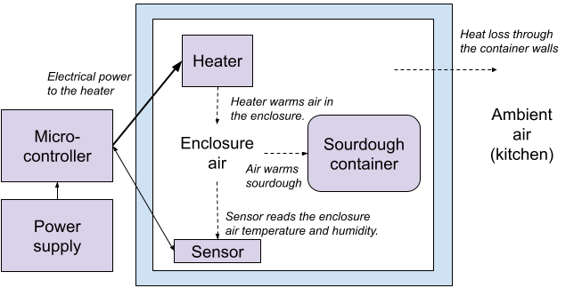
- Enclosure: An insulated space for the dough,
- Heater: Heats the air in the enclosure,
- Temperature/humidity sensor: Allows the controller to react to the conditions inside the enclosure,
- User interface: Used for enabling and disabling temperature control, setting the goal temperature, and monitoring the device,
- Microprocessor board: Implements the user interface and controls the conditions in the enclosure,
- Power supply: Powers the heater, sensors, and microprocessor board,
- Safety system: Ensures that problems with the overall system will not lead to overheating.
Hardware design
A large part of the system design is the identification and selection of its physical components.
Enclosure
The enclosure isolates the environment for the dough from the ambient air in the kitchen.
I first tried using a simple insulated food delivery bag5. This works, and is very inexpensive, but it is larger than necessary and there is significant heat loss through the fabric walls.
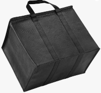
Here is an example of the power usage of the version with an insulated bag.
The system draws 70W at first as it rapidly comes up to the target temperature, then eventually
settles to slightly more than 20W.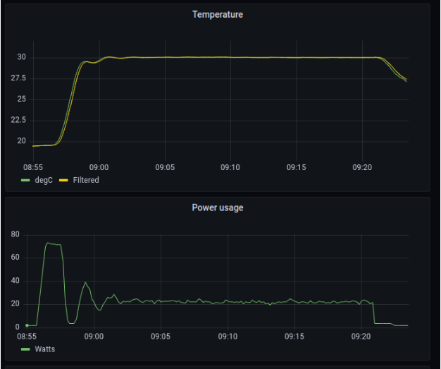
I switched to a small Coleman cooler6 instead, which requires less than half the power
to maintain the desired temperature.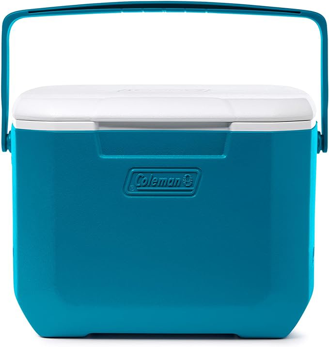
| Enclosure type | Power to maintain temperature |
|---|---|
| Insulated grocery bag | 21 W |
| Cooler | 8.5 W |
The cooler costs around $20 rather than 7.50 for the insulated bag, making it the most expensive component of the system.
The dough fits nicely into the enclosure along with the heater and sensor.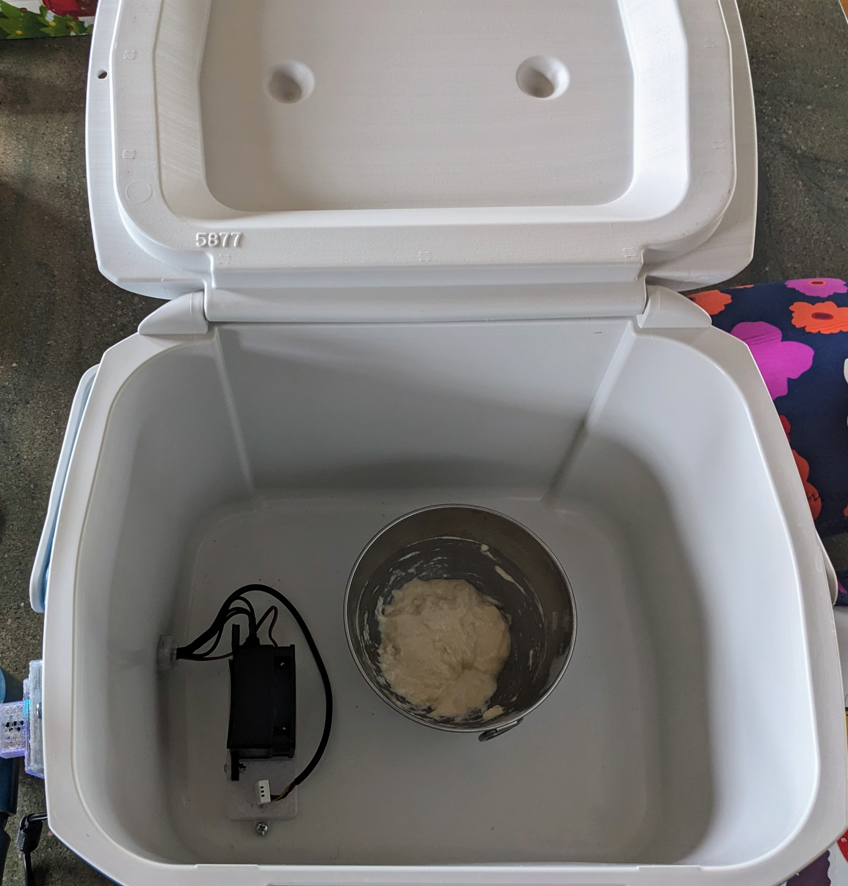
Heating and fan
A number of kinds of devices which might be used to heat the enclosure.
I could possibly have used a simple heating element or heat pad, but for now I’m using a PTC
heater7 with a fan.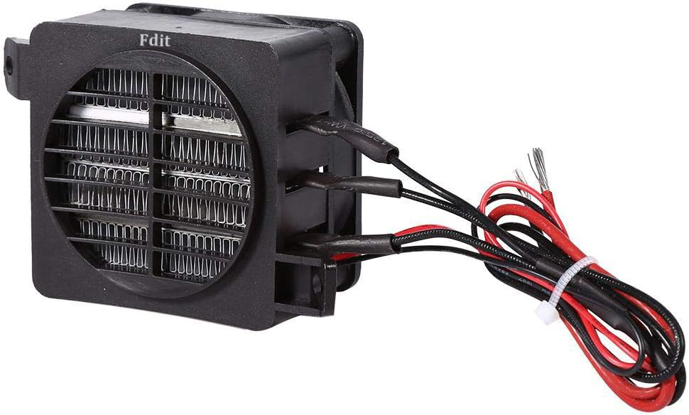
User interface
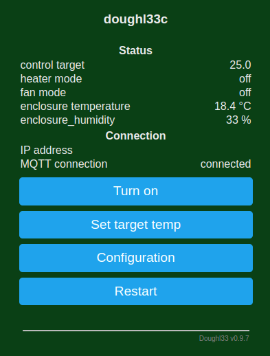
The system has both a physical user interface and a web interface.
It is also designed to optionally work with smart home systems via MQTT8
(see the
Home Assistant section).
The physical user interface is very simple: a small OLED screen and a simple push button
to enable and disable control of the enclosure temperature.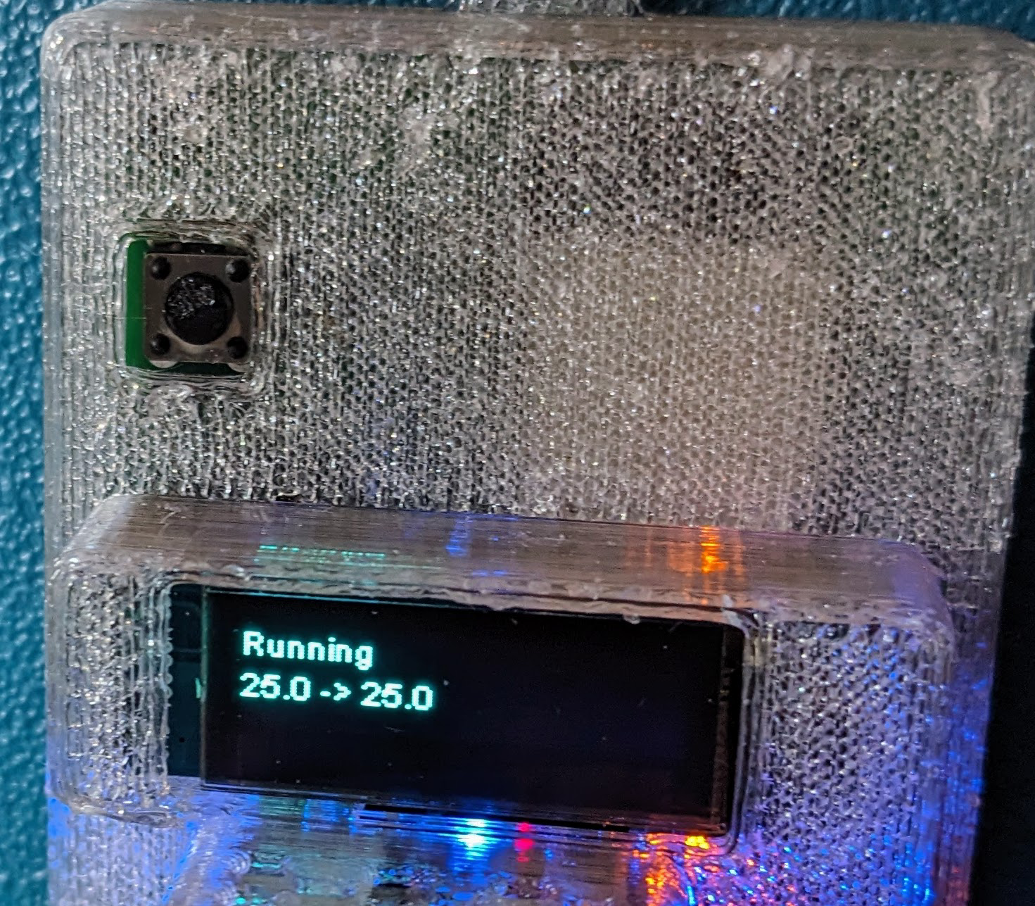
Sensors
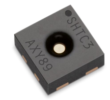
I use two SHTC39 temperature/humidity sensors for this application.
The SHTC3 is precise (±2 % relative humidity and ±0.2 °C), inexpensive,
and is easy to interface using
.
It works over a range of 0 to 100 %RH and temperatures from -40 to 125 °C.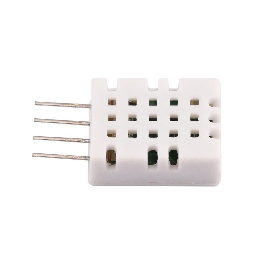
As discussed further in Temperature Control below, there are two sensors because the steady state power required to keep the enclosure at the desired temperature depends on the difference between the enclosure temperature and ambient temperature. If we lack a sensor for ambient temperature, we can instead measure the temperature of the enclosure before temperature control is first turned-on, and use that value as the ambient temperature thereafter.
Electrical design
The electrical design is covered in depth in Dough133 Electronics: Designing a Custom ESP32 Controller for Proofing Sourdough, but I summarize it quickly here.
- The brain of the system is an ESP3210 microprocessor. These are inexpensive, relatively powerful, have built-in WiFi, and a healthy ecosystem of open source libraries.
- Heater control is done using pulse-width modulation (PWM)11 with a MOSFET12 (a fast solid-state switch) and a flyback diode13.
- Fan control is similar to the heater control with a MOSFET and flyback diode, but its control is much simpler. The fan is run at full power while the heater is in operation. It is turned-off 90 seconds after enclosure temperature control is ended.
- Power is provided by a 12V A/C adapter, and converted to 5V by an integrated buck converter14 and to 3.3V by an LDO15 voltage regulator.
- A safety circuit will quickly turn-off power to the heater if a digital heartbeat signal is not provided by the microprocessor. This was added after earlier versions of the system using an ESP826616 processor locked-up a couple of times, leaving the heater uncontrolled.
Software
I wanted to use C++ to program the microcontroller because I am familiar with it and it
is a well-supported language for this kind of application.
I use PlatformIO17 to compile and upload the firmware to the device.
From various projects I have worked on, including this one, I have built a C++ framework
that I like to use with ESP microprocessors.
I recently published this library, “og3”18, as open source on GitHub.
This library is also the basis for the software for the
Plant133 project from my previous blog post.
The present blog post is the first time og3 has been publicized, so at the time of
writing no one else has used this library.
The library supplies the infrastructure for the WiFi configuration, the
web interface, the MQTT interface, saving and loading configuration to/from flash memory,
and writing text to the OLED display.
3D-printed components
There are three 3D-printed custom components in the system:
- The EBox housing the PCB,
- A holder for the heater and temperature sensor inside the cooler, and
- A threaded plug to help seal around the wires running through the side of the cooler.
All printed components were designed using OpenSCAD19.
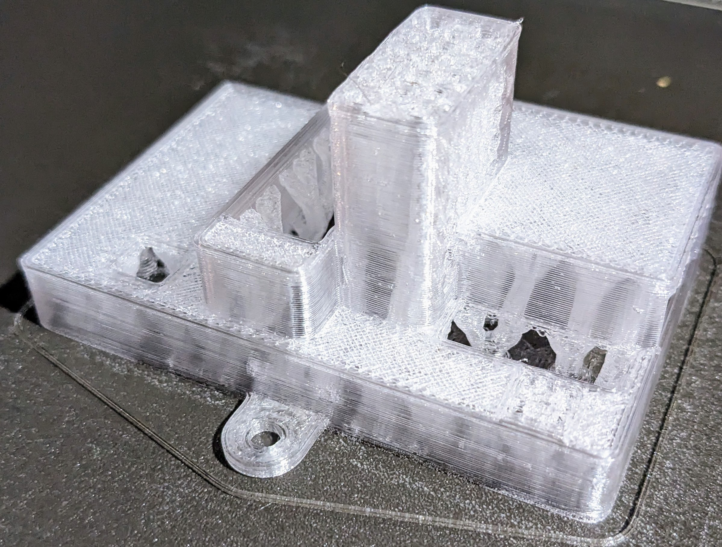
EBox
The EBox houses the PCB, and has raised “bumps” for the OLED screen, the MOSFETs, and connectors. This shape cannot easily be 3D-printed without supports, so the figure below shows how the top of the EBox is printed using “organic” supports. These are generated by PrusaSlicer, the program I use to turn the 3D model of the parts I want to print into instructions for my printer. The organic supports look like tree branches, and are removed with pliers after the part is printed. At first I printed this part upside down, but the top surface finish is better when printed with the supports below. I recently moved the screw-tabs from top and bottom to the sides of the box to keep the top mounting screw away from the WiFi antenna of the ESP32 module.
Heater holder
The heater holder is a bit of plastic the heater is bolted onto and the temperature
sensor mounted in, and which can be screwed to the bottom of the cooler to keep these
components in place.
The 3D model for this, and the model of the heater I used for designing the holder, are
shown in the figure below.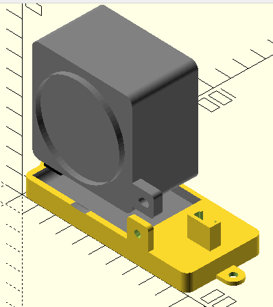
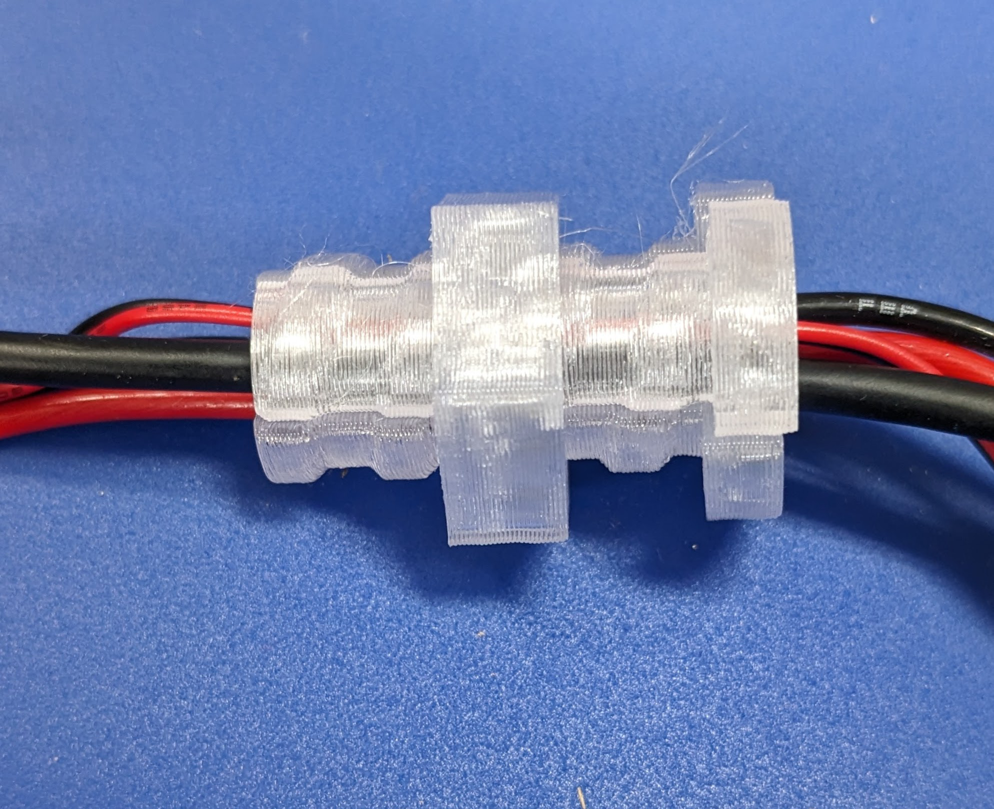
Cooler plug
Wires to the heater, the fan, and the temperature sensor need to run from the EBox mounted on the outside of the cooler to the heater holder on the inside. A hole is drilled through the wall of the cooler for this purpose. To slow the loss of heat through the hole, and to make it look slightly better, I designed a plug to hold the wires.
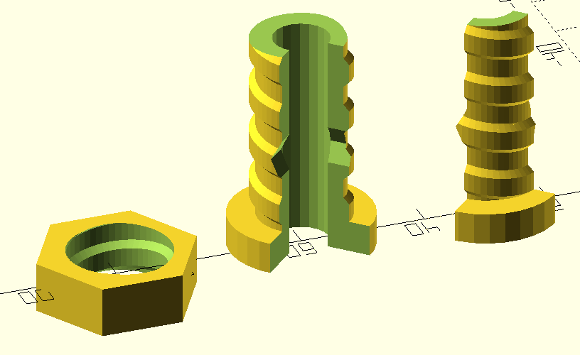
The plug is printed in two parts which can be pressed together with the wires between them, then inserted into the hole from the outside of the enclosure. The outer side of the plug is threaded so that a printed nut can be screwed onto its end from the inside of the enclosure. This holds the plug in place and better seals against the wall of the cooler.
Temperature control
Control of the enclosure temperature is one of the more interesting parts of the project. It is now documented in the follow-up post Dough133 Control: Yeast Welfare through Applied Mathematics.
Home Assistant
The og3 library used to write the software for this project makes it easy to interface
a device like Dough133 with Home Assistant20.
If you have a Home Assistant instance and an MQTT broker in your home, you use the web
interface to tell the device how to talk to the MQTT broker.
Then, a set of sensors and a thermostat control for Dough133 will automatically be
discovered by the Home Assistant instance.
The thermostat widget that Home Assistant offers for controlling our device is shown below.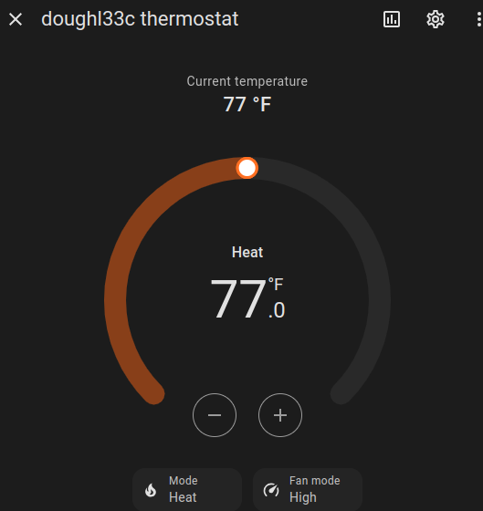
Safety system
Before I developed the safety circuit on the controller board, I used a smart plug with the Home Assistant system in my house to implement a simple power cut-off mechanism for safety. The smart plug measures power supplied to the device and can be switched on and off by Home Assistant. The home automation system adds-up the power supplied to the device over 15 minutes. If this value gets too high, an automation rule switches the smart plug off.
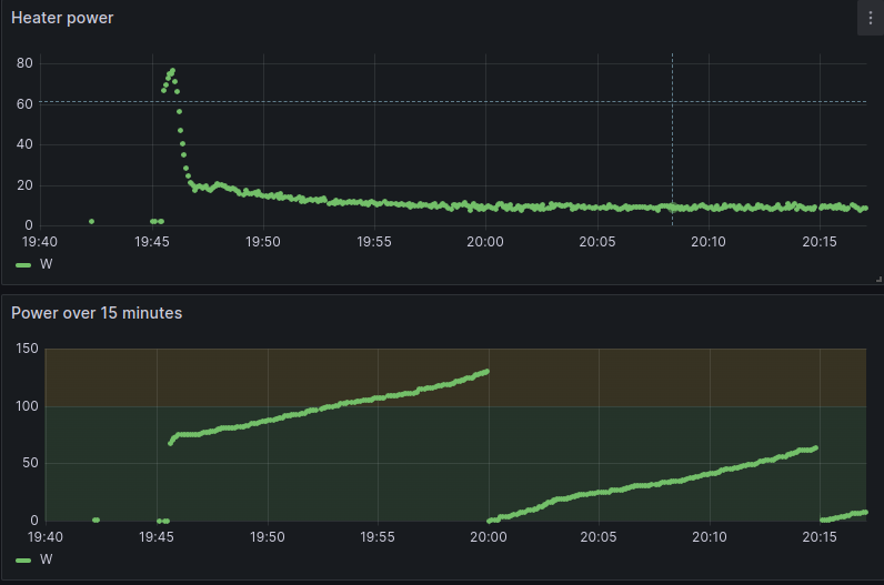
I found by experimentation that when things are working normally, the integrated power should not get above 100 (the scaling of these values is arbitrary, not SI units) over 15 minutes. So I have the system send a warning to our phones if the value gets above 125, and cut power if the value gets above 150.
Evaluation
Material cost
Here is a rough breakdown of the cost of materials for making a single Dough133 device. These are ballpark estimates since the prices vary over time and by vendor. It is cheaper than the fancy commercial systems, though lacking features like humidity control. It costs quite a bit more than a small light bulb in a Tupperware container.
| Component | Cost |
|---|---|
| PCB (4 layer, lead-free finish) | $3 |
| Total PCB electronics components (est) | 10 |
| PTC Heater | 7 |
| Cooler | 20 |
| 12V A/C power adapter | 12 |
| Printed components | 4 |
| Total | $56 |
Thermal performance
This is a thermal image of the system in operation.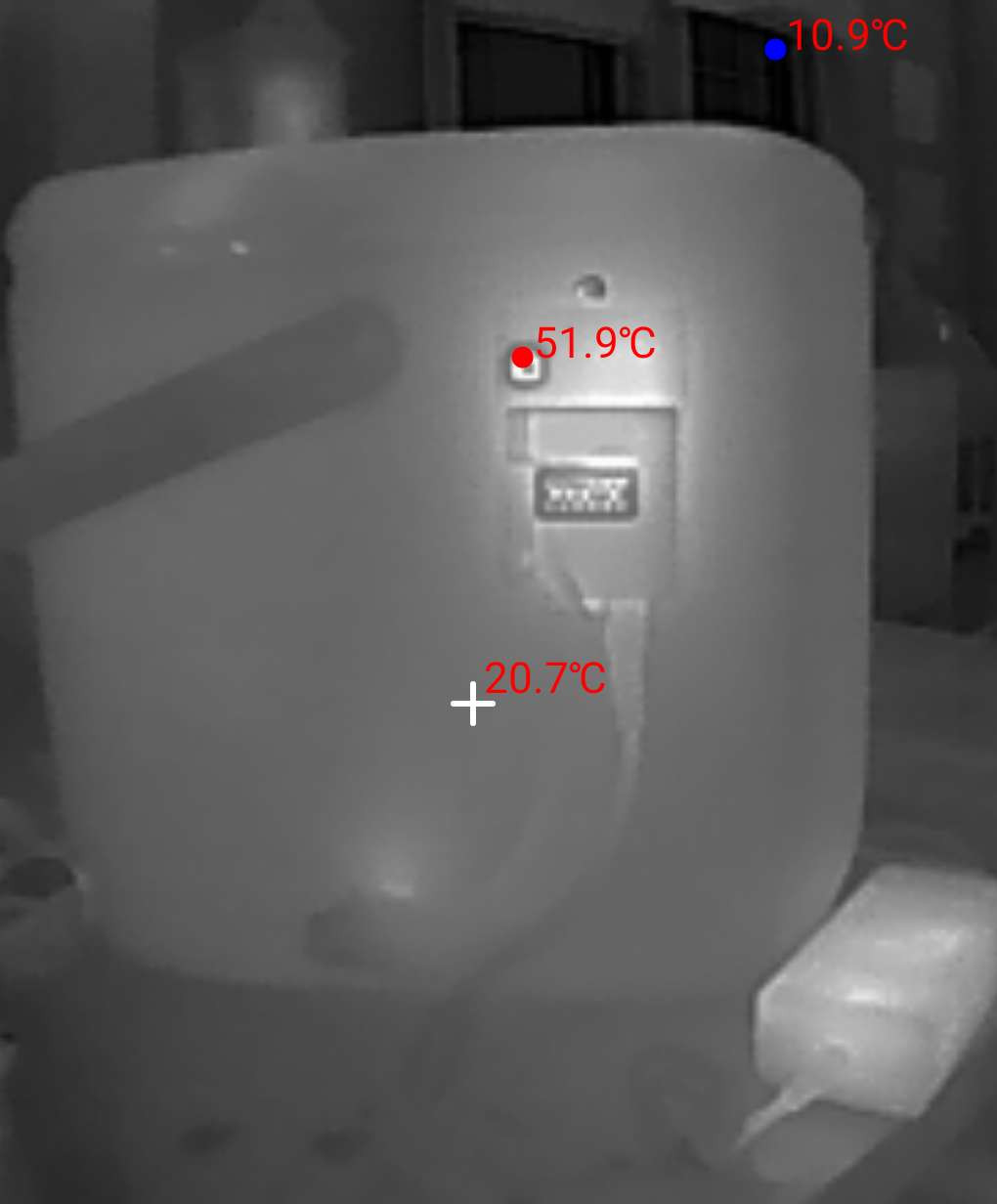
We do want heat to escape from the EBox, to keep components like the microcontroller from getting too hot. Heat is generated by the MOSFETs used to control power to the heater and the fan, the microprocessor, the WiFi antenna, the power regulators, and the OLED display. The hottest location in the image of the EBox is actually the hole exposing the push-button, where warm air escapes from the EBox. This suggests it might be a good idea to add some air vents to the top of the EBox, which should be more effective at letting heat escape. The microprocessor is visible to the right of the push-button, near the top of the EBox. The 12V power supply to the right of the cooler is also an obvious source of heat.
Here is a view of the EBox when the system has recently been turned-on and the heater
is near full power.
The hottest component is the MOSFET controlling power to the heater.
It is below the microprocessor, near the middle of the picture.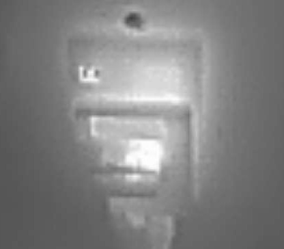
Future improvements
I’m happy with the system as it is working now, so don’t have plans to make major changes. If you know of ways it might be improved however, I’d be interested to hear!
References
Proofer and slow cooker by Brød & Taylor. ↩︎ ↩︎
Insulated Reusable Grocery Bag which was $15 for 2 at the time. 16”x10”x12” high. ↩︎
Constant Temperature Air Heater 12V100W ( AliExpress $7). ↩︎
The MQTT protocol ( Wikipedia) is useful for IOT (Internet of Things) applications. ↩︎
SHTC3 module ( AliExpress) ( Datasheet) ↩︎
ESP32: a family of microcontrollers made by Espressif Systems. A successor to the ESP8266 microcontroller. ↩︎
Pulse-width modulation (PWM) is a method of representing a signal as a rectangular wave with a varying duty cycle (ratio of “on” to “off”) Wikipedia. ↩︎
MOSFET. The metal–oxide–semiconductor field-effect transistor (MOSFET) has the ability tochange conductivity with the amount of applied voltage, and can be used for amplifying or switching electronic signals. Wikipedia. ↩︎
A flyback diode is any diode connected across an inductor used to eliminate flyback, which is the sudden voltage spike seen across an inductive load when its supply current is suddenly reduced or interrupted. It is used in circuits in which inductive loads are controlled by switches, and in switching power supplies and inverters. Wikipedia. ↩︎
A buck converter is a DC-to-DC converter which decreases voltage, while increasing current, from its input (supply) to its output (load). It is a class of switched-mode power supply. ( Wikipedia). ↩︎
A low-dropout regulator (LDO regulator) is a DC linear voltage regulator that can operate even when the supply voltage is very close to the output voltage ( Wikipedia). ↩︎
ESP8266: a low-cost WiFi microchip, with built-in TCP/IP networking software, and microcontroller capability, produced by Espressif Systems. ↩︎
PlatformIO is an open source framework for compiling/uploading embedded software, and managing libraries used by this software. ↩︎
og3is my C++ utility library for ESP microprocessors, published on GitHub. ↩︎OpenSCAD is an open source program implementing a programming language for building 3D models. It is a way to build models using solid modeling primitives. ↩︎
Home Assistant is a popular Open Source home automation platform. It is the hub for my own smart home, and it is fun to work with. ↩︎