Dough133 Assembly: Building a DIY Sourdough Proofer
Posted on September 29, 2024 • 11 min read • 2,181 words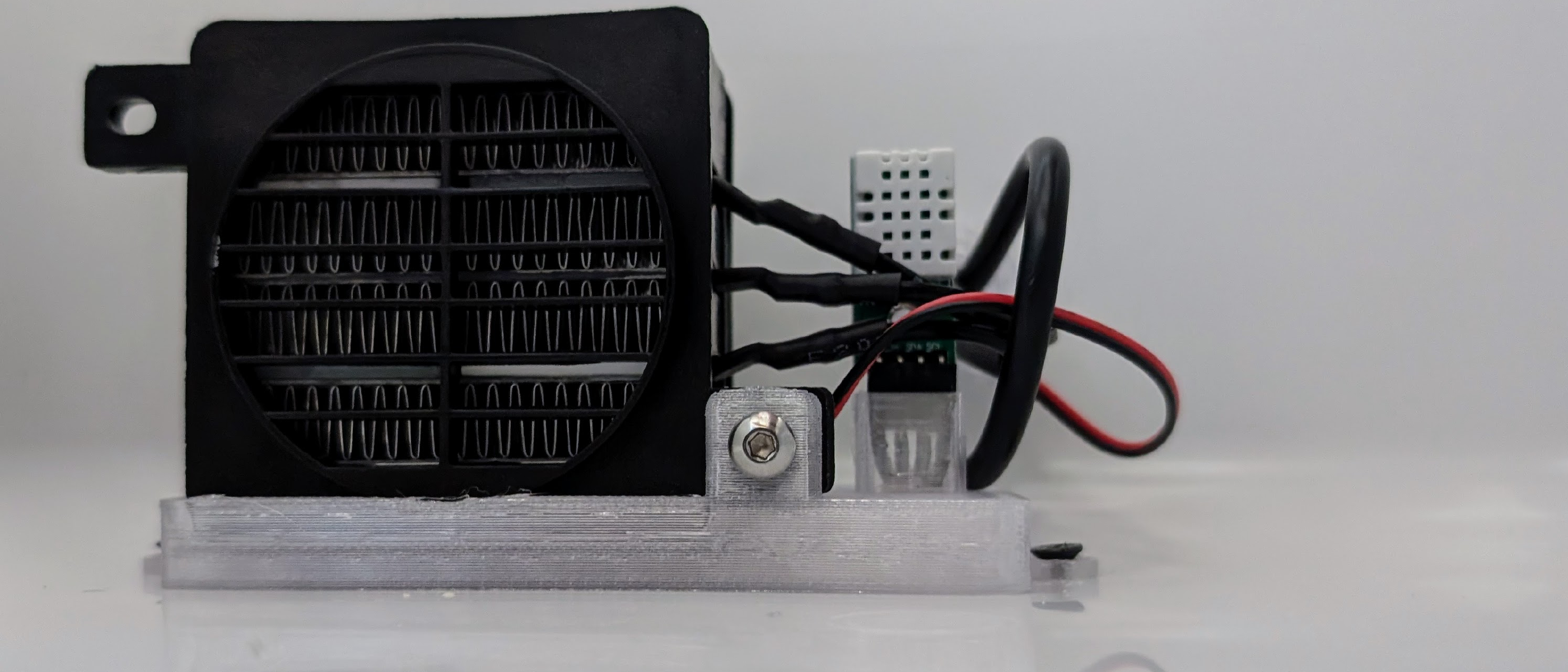
Introduction
Dough133 is a heated enclosure I built for proofing and fermenting sourdough. After many iterations on the hardware and software design, I am fairly happy with it. The evolution of the electronics design is documented in Dough133 Electronics.
When I order printed circuit boards (PCBs) for projects like this, the minimum quantity is 5 boards. Since it is more satisfying to have built a few devices before I “retire” the project, and because I have plenty of components in stock, I built a couple extra devices to give away. After going through the assembly process a couple times, I figured it was time to document it here.
The KiCAD1 design files for the circuit board, the OpenSCAD2 files for 3D-printed components, and all source code for the firmware are on GitHub with an MIT license at https://github.com/chl33/Dough133.
It should be possible for a determined person to make their own Dough133 using this repository and these instructions.
Parts List and Sourcing
The main items which need to be purchased, along with a link and approximate prices as of September 2024:
| Item | Source | Approximate cost |
|---|---|---|
| Coleman 16 qt cooler | Amazon | $23 |
| PTC Air Heater 12V 100W | AliExpress | $7 |
| DC 12V 5A Power Supply | Amazon | $12 |
PCB Assembly and Soldering
Update: Since I wrote this post, I’ve improved my process for PCB assembly. Please also see my later posts DIY SMD PCB Assembly: Tools and Organization for Hobbyists and Improved PCB Stencil Alignment with 3D Printed Fixtures.
I used JLCPCB3 to make this circuit board. I generated Gerber files in KiCAD, uploaded these in a zip file to the JLCPCB web site, then ordered the boards.
I haven’t yet tried having my boards assembled by the PCB manufacturer. I still assemble them myself.
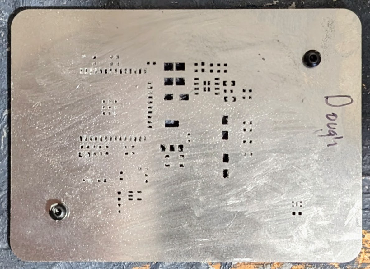
Using Solder Paste Stencils
Solder paste is a combination of solder and soldering flux. Flux is an agent which helps melted solder flow into the right place. When melted and then cooled again, solder paste connects surface-mount components to a printed circuit board both physically and electrically. While surface-mount components are initially placed onto the board, before the board is heated to melt the solder, the solder paste is slightly sticky and thus holds these tiny items in their correct locations on the board. I order my PCBs lead-free, and I use lead-free solder paste.
I found it difficult to figure out what kind of lead-free solder paste to order by just Googlng about it. Eventually I tried low temperature Chip Quik solder paste, and more recently I’ve had good results using solder paste with a 183°C melting point from AliExpress. I’ve had fairly good results with each.
I typically order my PCBs with a stencil for applying solder paste. At first I was hesitant to order these since the shipping cost was so high. Instead, I tried to use a syringe to apply solder paste onto pads in the right places on the board. This was difficult, time consuming, and the results weren’t very good. So I started ordering stencils with the boards. Later I read that you can order stencils trimmed to size so they fit in the same box as the PCBs, so there is no extra shipping cost. I design the solder stencil with holes matching the board’s mounting screw holes. I can then screw the board in place under the stencil so that all pads line up precisely with the holes in the stencil, and the stencil stays securely pressed against the board.
SMD Component Placement
When I started assembling boards with surface-mount components, I found it to be a very
slow process to select SMD components and place them in the correct position.
The components are very small, so I place them using tweezers while looking through a
stereo microscope.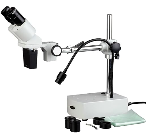
Over time, I’ve found that I can 3D print trays with pockets for commonly used components. I extract many components into these pockets at once, clearly label the pockets, and label components on the board in ways to make it easy to identify components without needing to consult diagrams. For example, my circuits use many 100nF capacitors, so I label these on the board “Ca1”, “Ca2”, etc…. I use “Cb1” and so on for 10µF, “Cc1” for 47µF, etc… since these are also common in my designs. Similarly, I often use resistors with values 10kΩ, 470Ω, 1kΩ, etc… so use labels for these to make them easy to place. I have a bunch of SMD components and modules I’ve bought in bulk very inexpensively, mostly from AliExpress. For more specialized components, or ones where I’ve been unhappy with the very cheap versions from AliExpress such as some voltage regulators, I order from Digikey.
Reflow Soldering Process
At first, based on a couple YouTube videos, I used a small hot plate to solder SMD components
onto my boards.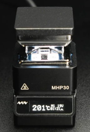
I got poor results, possibly because of my inexperience.
Eventually I bought an inexpensive T-962A reflow oven and followed some
instructions on the Internet
to improve its quality and reliability.
I’ve achieved much better results by using this oven.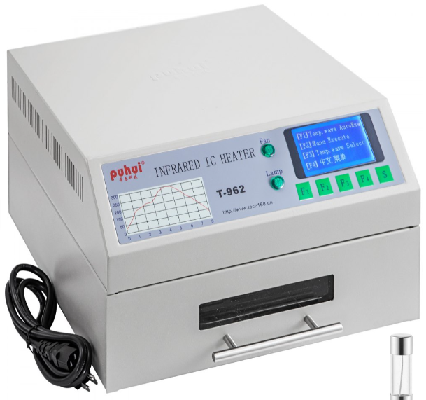
Step-by-Step PCB Assembly Guide
This is the process I used to build a PCBA.
- Screw the PCB onto the solder-paste stencil.
- Use a solder paste syringe to deposit paste around the holes in the stencil, then use a putty knife to make sure all holes in the stencil are filled.
- Remove the board, then clean the stencil with alcohol and a Q-tip to so no solder paste dries in the holes between uses.
- Place the PCB in clamps under a microscope, to prepare for assembly.
- Pick components out of the SMD component trays to populate the board. Place them with tweezers, looking under the microscope, using the solder paste to stick them into place.
- Place the board in the reflow oven and run an appropriate heating profile for your solder paste. This takes just a few minutes.
- Clamp the soldered board back under the microscope and inspect and test the soldered connections. Make fixes with a soldering iron if needed.
- Place through-hole components, headers, and other connectors on the board, and use blue-tack to hold them in place.
- Clamp the board upside down, and solder the pins onto the board to make connections and secure the components.
- Connect power to the board, and check that regulated voltages are correct.
- Clean the board with a small brush and some alcohol.
After this, I:
- Use my edge-connector board to power and program the ESP32 module from my laptop.
- Make sure software can talk to the sensors on the board, and run test routines via the device’s web interface to make sure the board is working correctly.
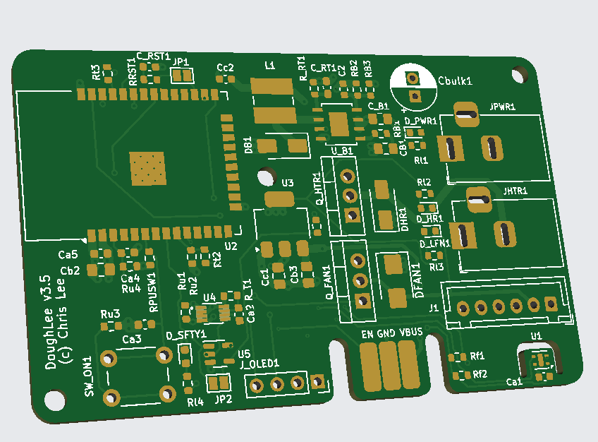
Below is a picture of the assembled Dough133 board with all SMD components, connectors,
and through-hole components.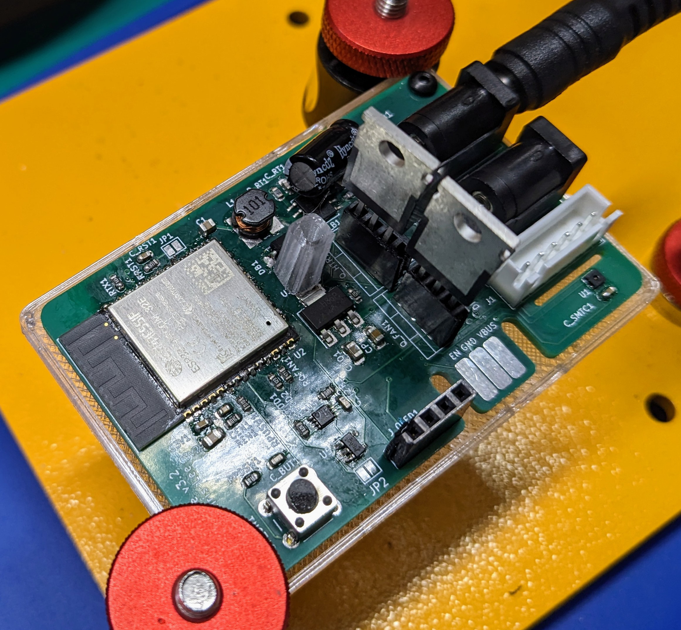
The header at the bottom of the board next to the edge connector is for the OLED screen. A 3D-printed spacer is attached to the board with a screw above this to support the middle of the screen when it is in place.
Installing 3D Printed Parts
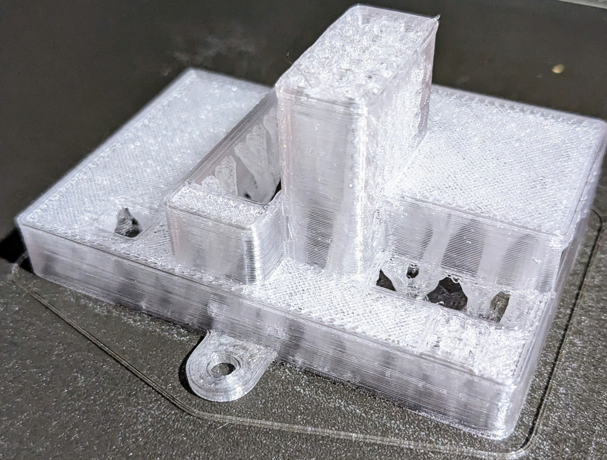
EBox
The EBox is designed with my ProjectBox system (see my Room133 Project Box post). To make a good finish for the top surface of the EBox, the top of the box is printed top-side up using organic supports underneath. I print the box using transparent PETG filament. It takes some care to remove the support material without damaging the box.
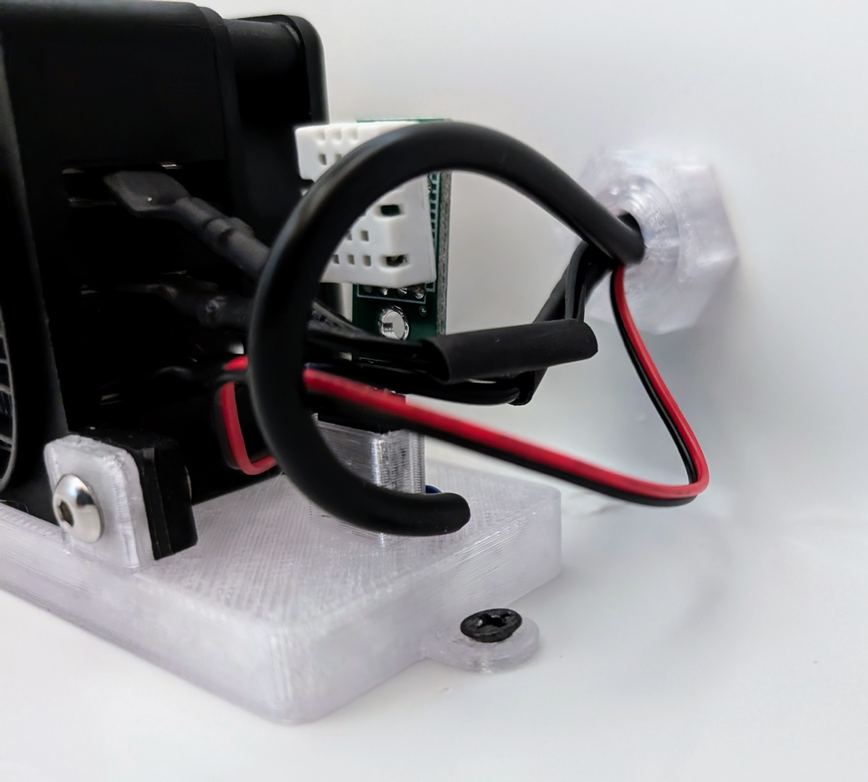
Mount for heater and temperature sensor
Using the same material, I print a mount for the heater and the temperature sensor, to hold them in place inside the cooler.
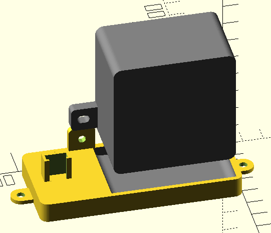
The heater is attached to the mount with a M4 10mm screw and a nut.
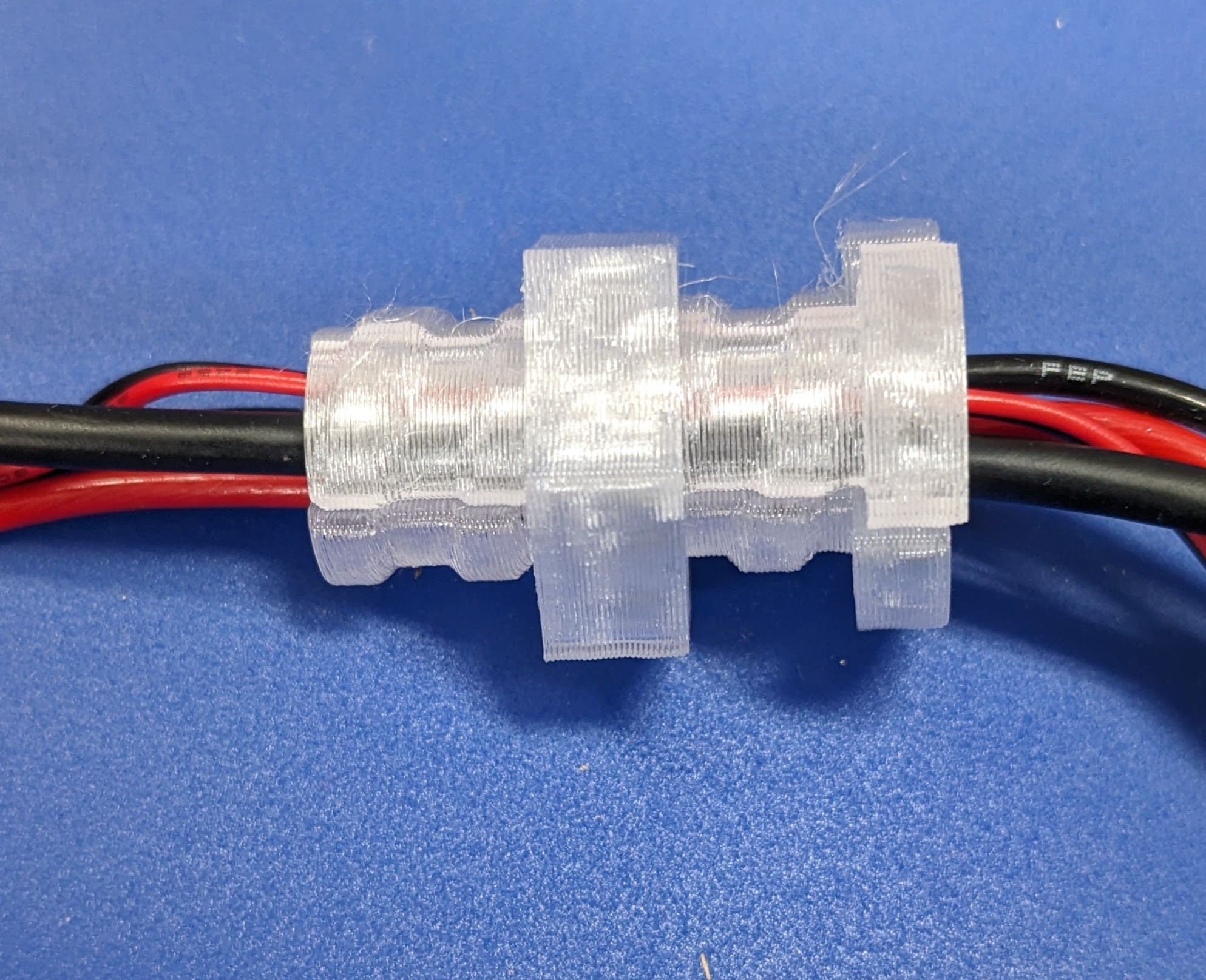
Cooler wiring plug
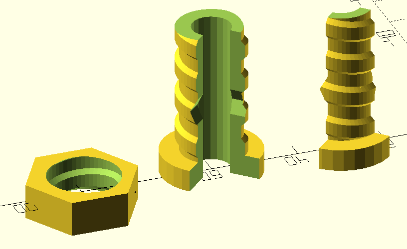
To help avoid heat escaping from the cooler, and to improve the appearance of the hole that will be drilled into the side of the cooler for wires to pass through, I print a 3-part plug that will surround the wires as they pass through the side of the cooler.
Wiring the Heater, Fan, and Sensors
Wire and connector assembly
The heater has one wire with two conductors for powering the heating element, and another wire with two smaller conductors for powering the fan. These wires will be routed through the side of the cooler to the EBox. I prepared an additional 4-conductor wire so the EBox can communicate with the temperature sensor inside the cooler. I cut this wire to be the same length as the heater’s fan wire. The 4 conductors are soldered to the bottom of a 4-socket Dupont header. I use heat-shrink to cover the solder joints.
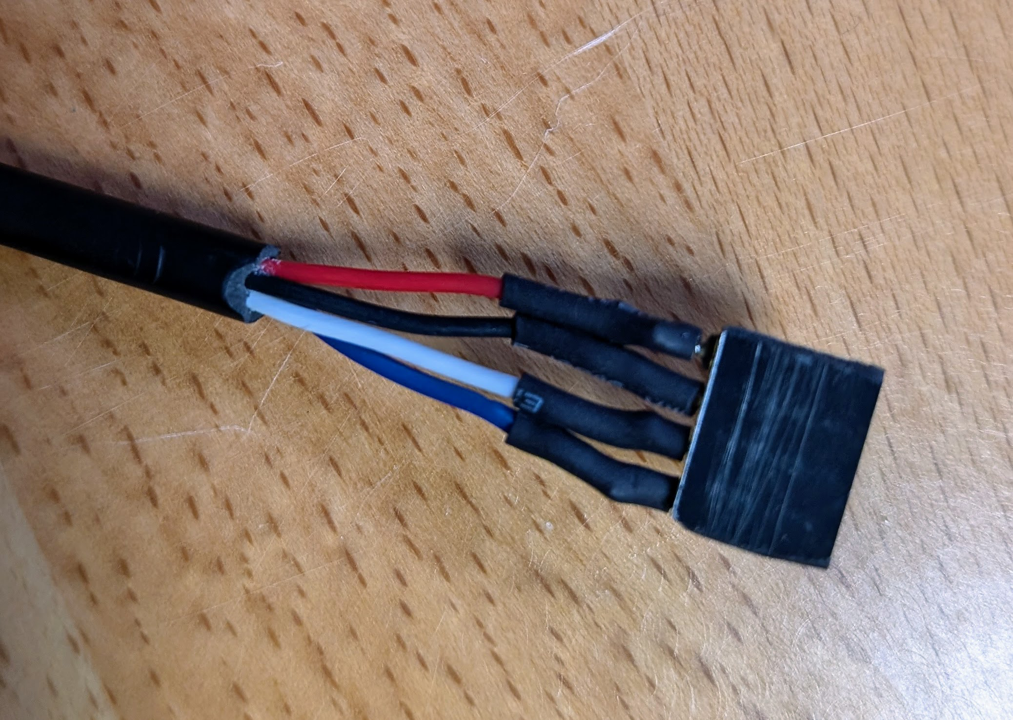
The header is then mounted in the insert.
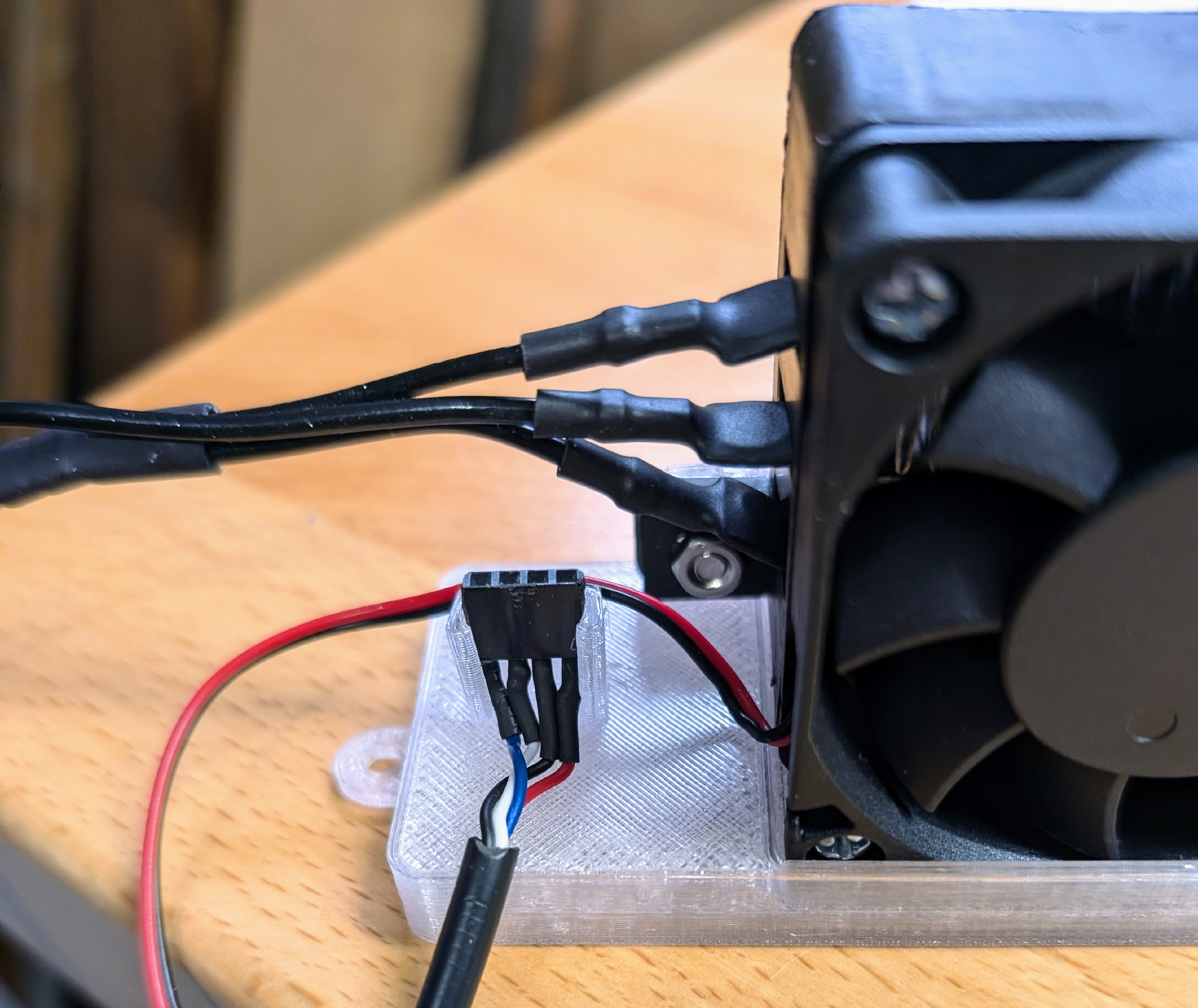
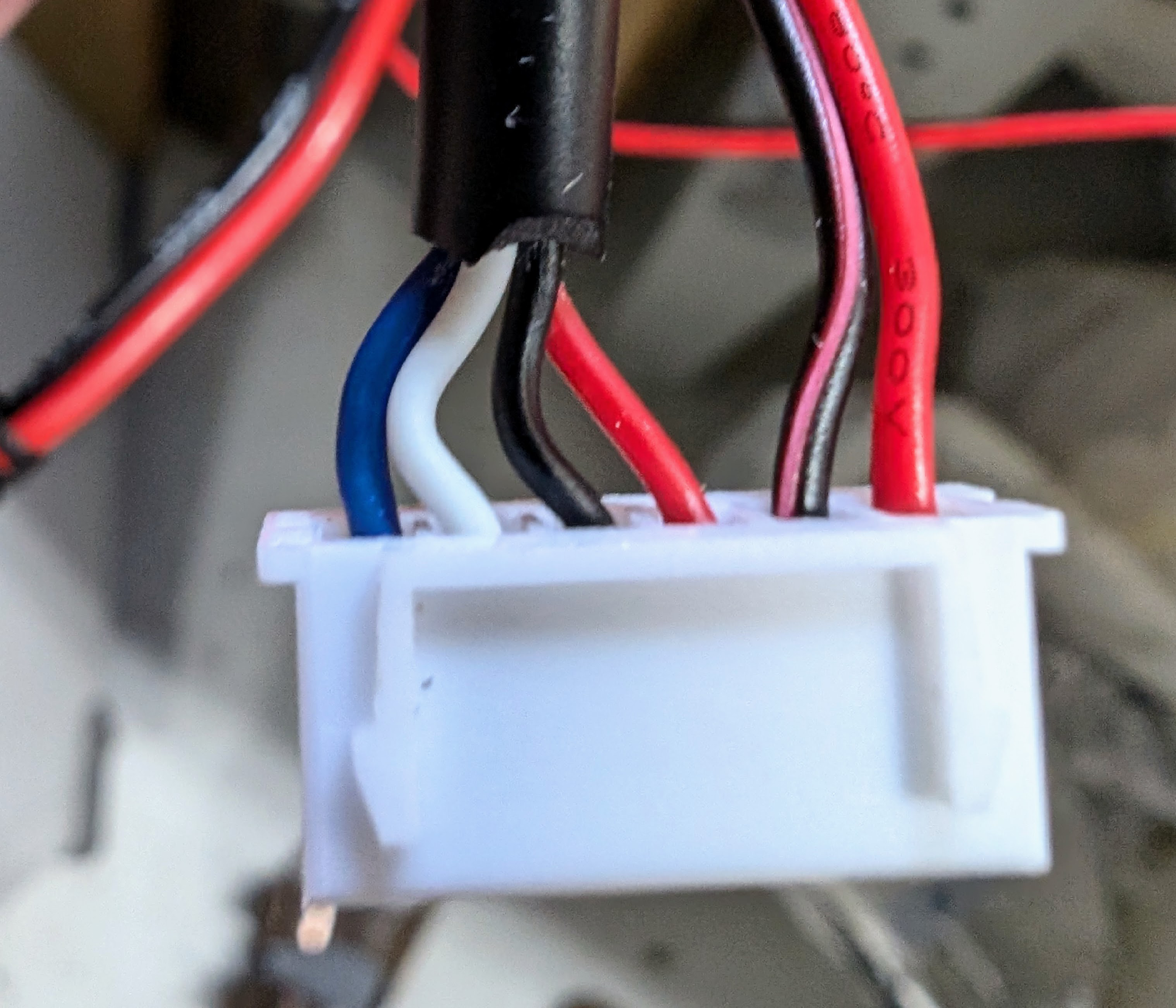
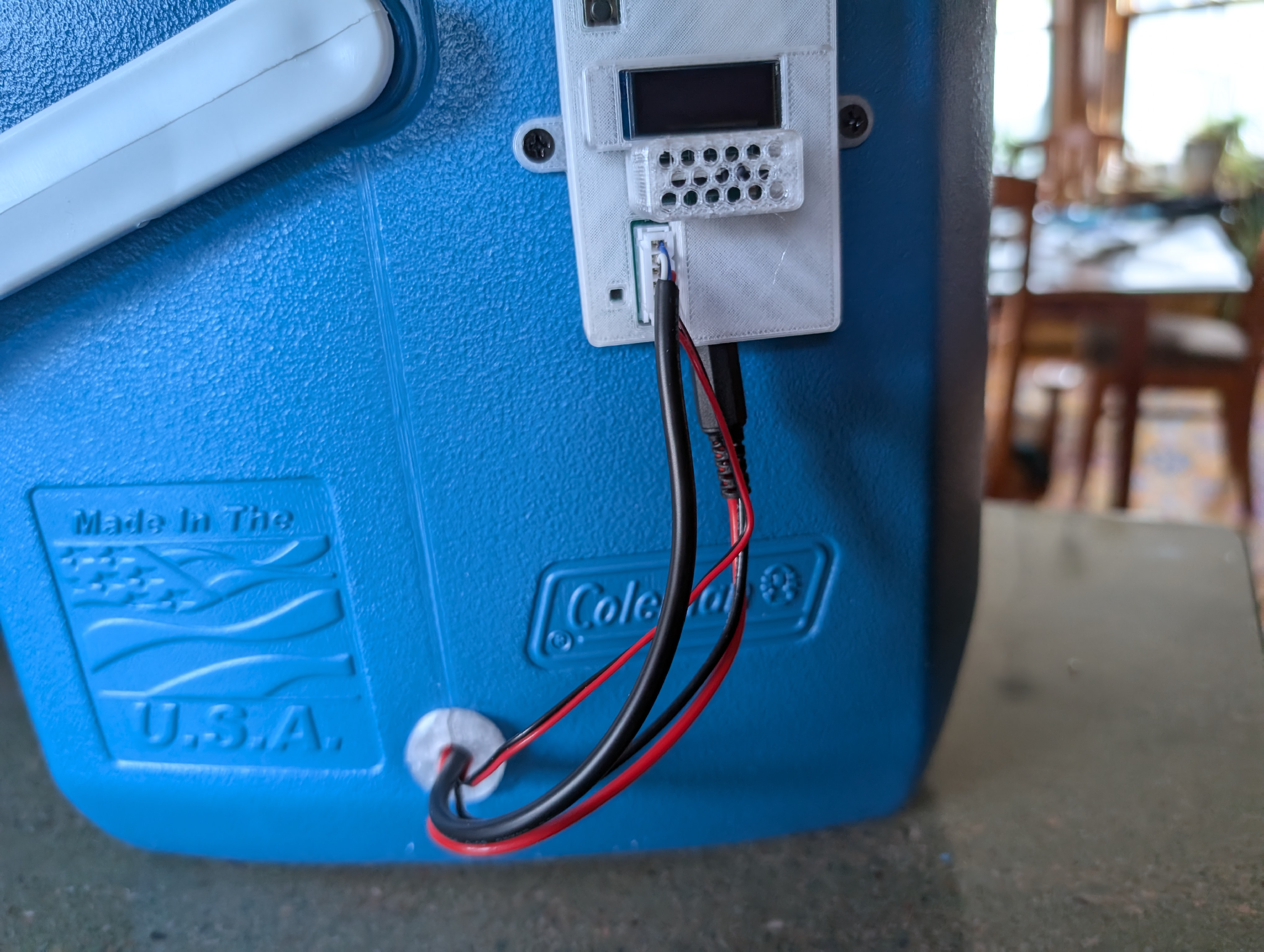
A single 6 socket female JST connector is placed at the other end of both the temperature sensor wire and fan wire. As shown below, from right to left, the heater +5V wire is inserted first, then the heater ground wire, then the four temperature sensor conductors in the same order as they are attached to the Dupont header on the other end. This connector plugs into the 6-pin JST connector on the EBox.
A barrel connector is used to connect the heater wires into the EBox. The wires are first soldered to the middle and outer conductors of the barrel, as shown below.
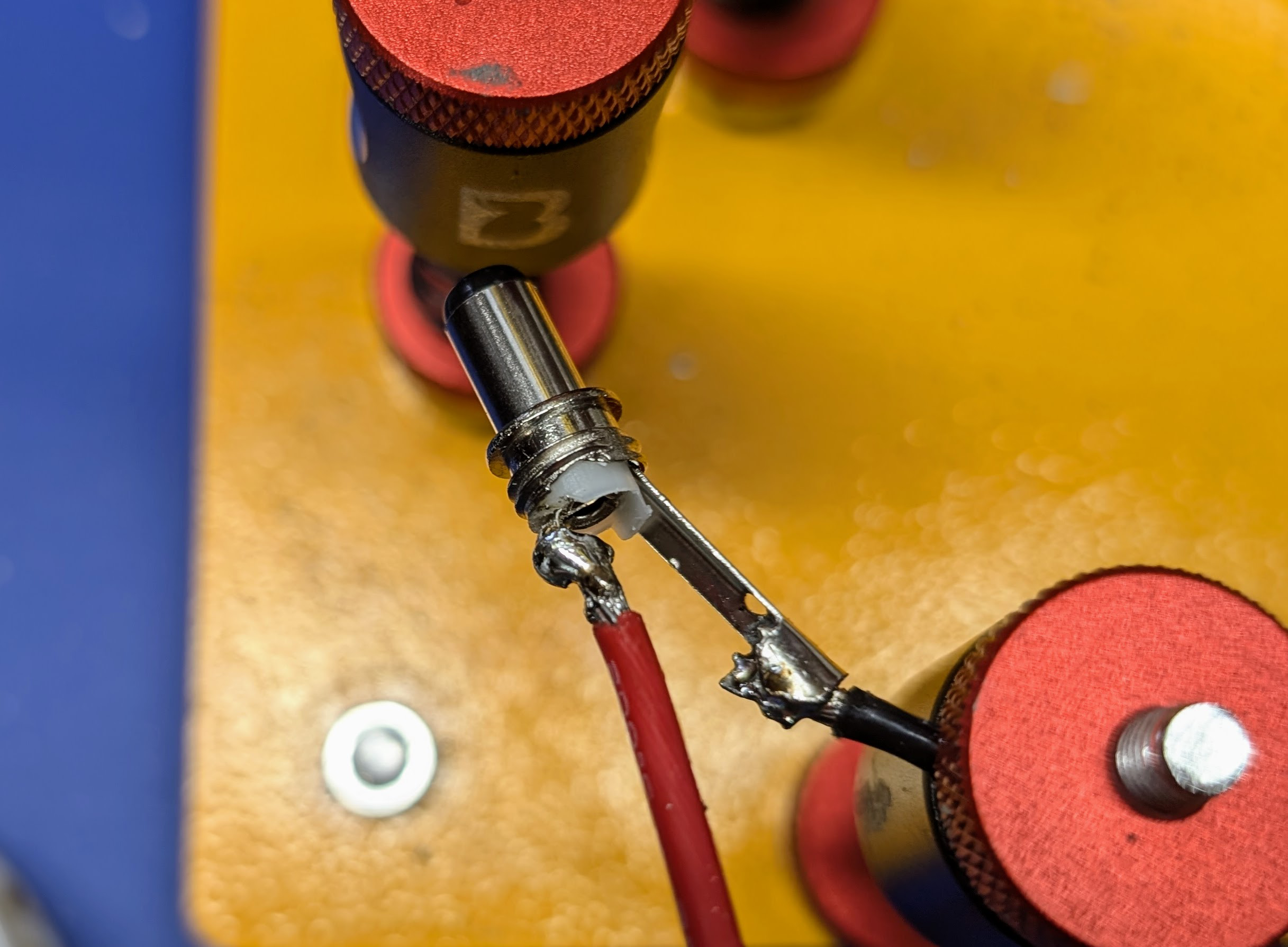
Before the wires are soldered to the barrel connector, the connector cover and heat shrink tubing are placed on the wires and pushed away from the end where the soldering will be done. After the soldering is finished, the heat shrink tubing slid into place to protect the solder joint. The tubing is heated with a heat gun to shrink it so that it stays in place.
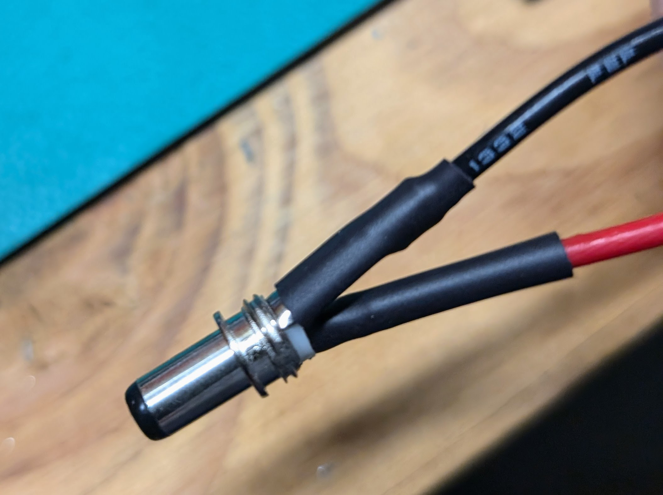
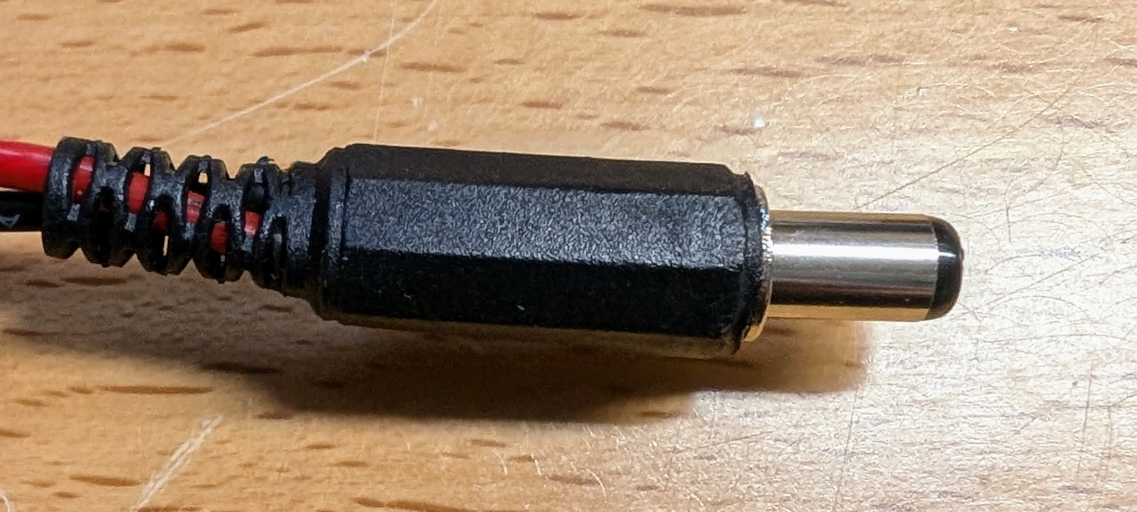
Next, the cover and strain relief for the barrel connector is slid into place and screwed onto the barrel connector.
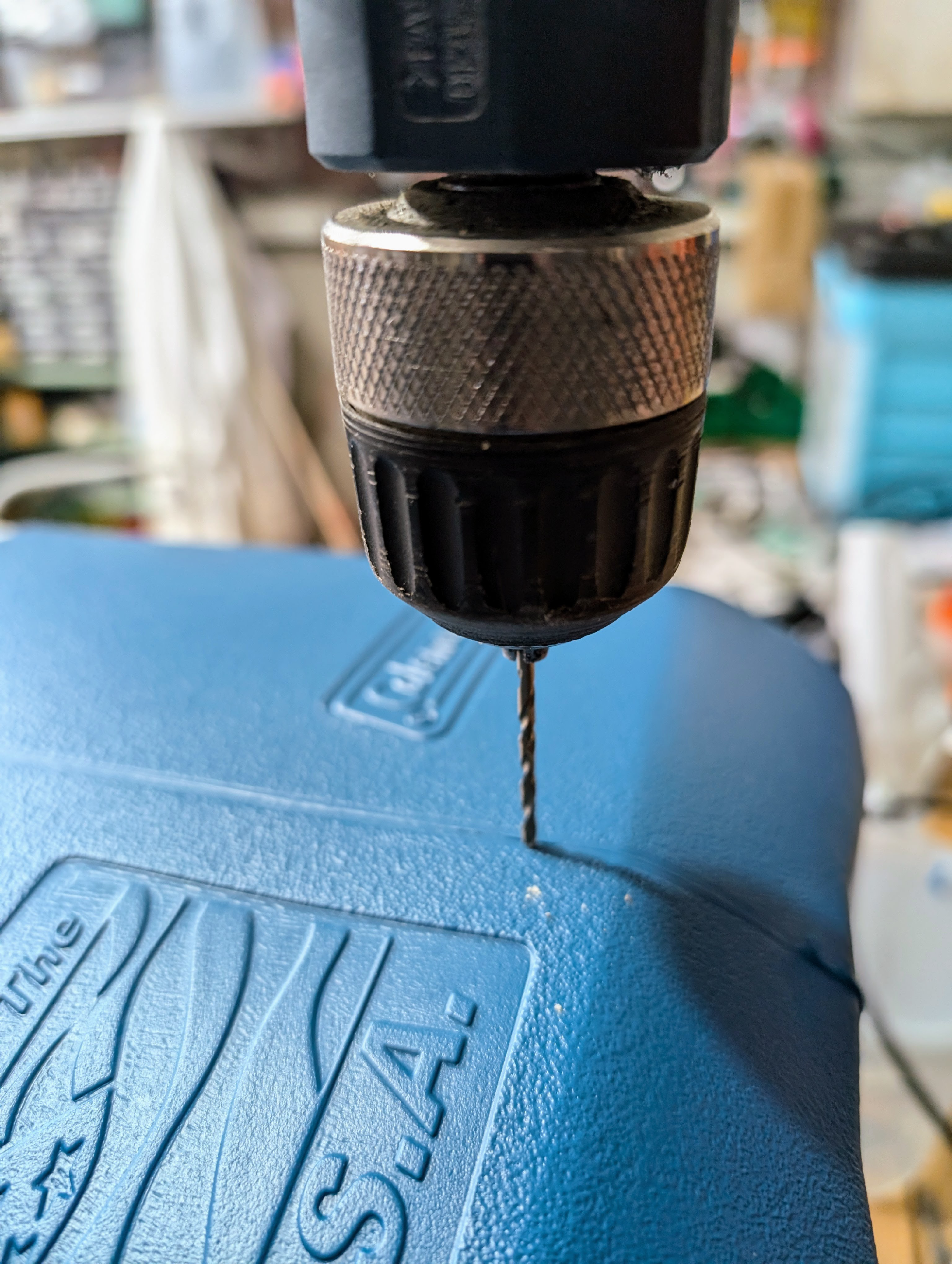
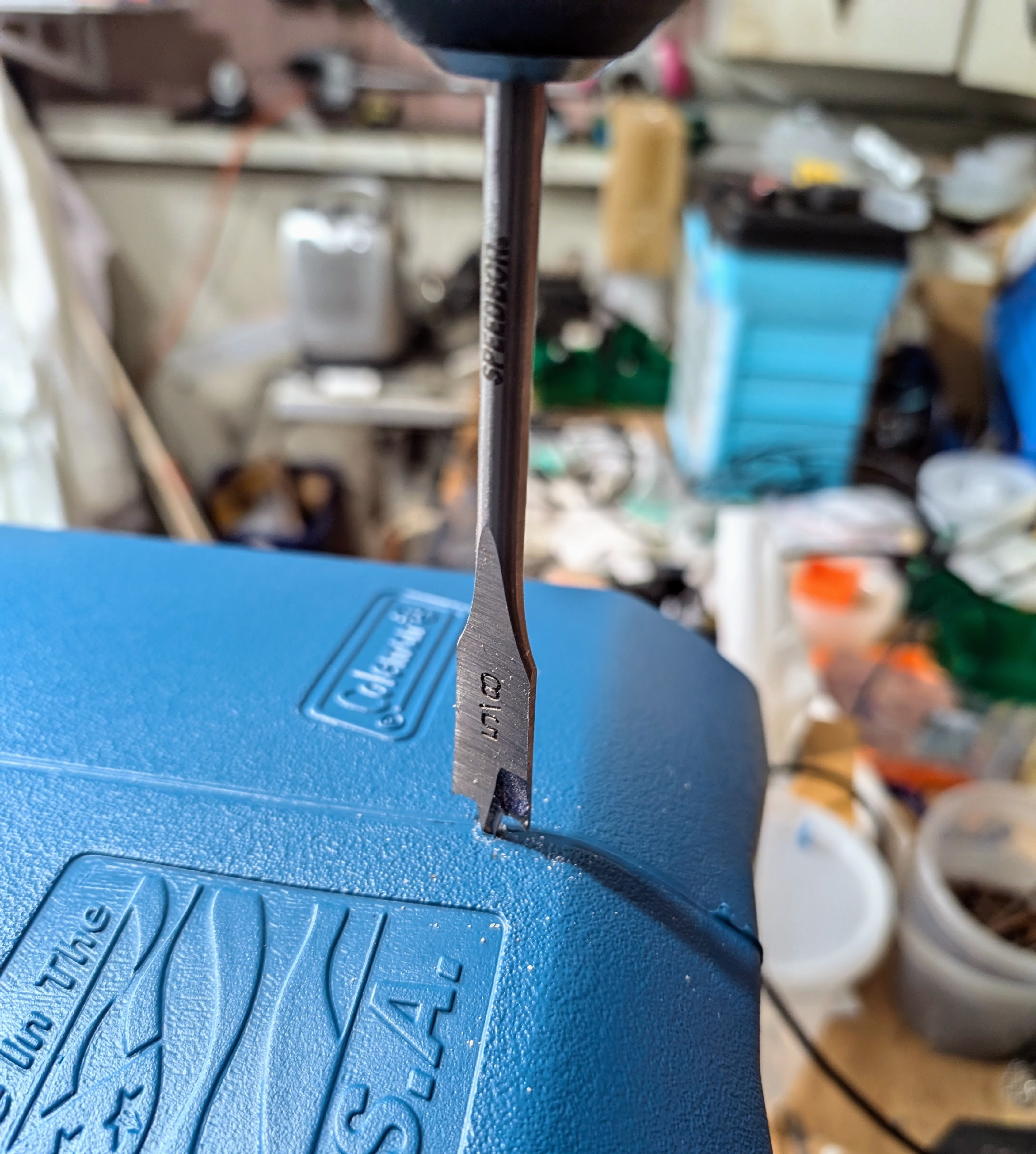
Running wires through the cooler
We need to run wires and connectors from the heater, fan, and sensor inside the cooler to the EBox on the outside. To do this we drill a large enough hole through the side of the cooler to pass the connectors through. We drill a pilot hole and then use a 5/8" bit to expand the hole.
Then we insert the wires from the inside of the cooler through the 3D-printed nut, then through the side of the cooler to the outside. We can then connect the two pieces of the cooler plug together around the wires from the outside, slide that though the cooler side, and thread the nut around that from the inside to hold everything in place.
Final Assembly: Securing the Heater Mount and EBox to the Cooler
Securing the heater mount
Wood screws can secure the heater mount to the floor of the cooler near the hole where
wires run through the cooler wall.
Attaching the EBox to the cooler
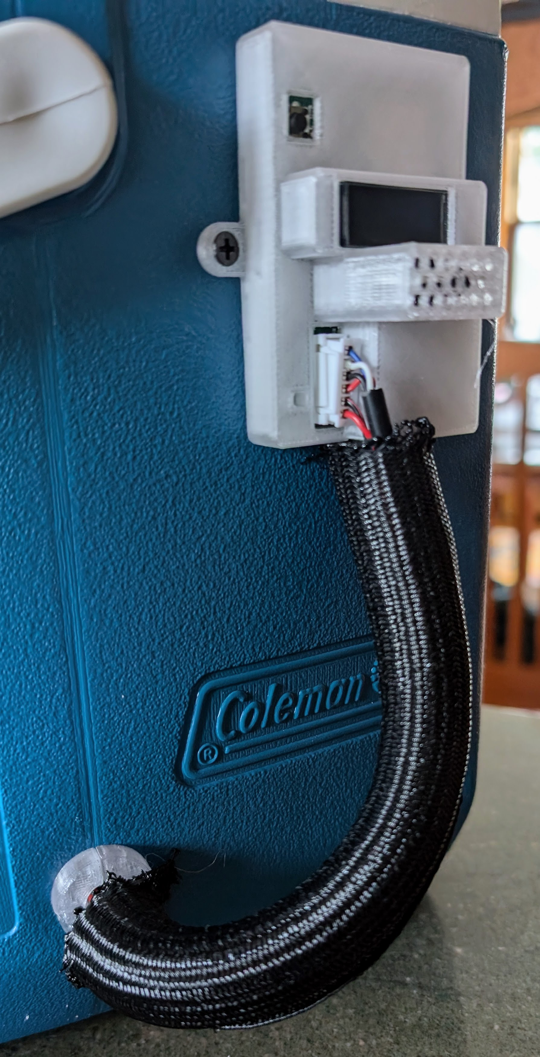
The EBox is attached to the outside of the cooler using small wood screws. It should be placed near the top of the cooler for easy access. Make sure the wires from the inside of the cooler are attached to the EBox when placing the box, to make sure the wires are not tight but also don’t have too much slack.

Cable sleeve can be cut and wrapped around the wires to keep them neat and in place. Use a match or lighter to melt the ends of the sleeve to keep them from fraying.
Testing the device
At this point, the Dough133 device is fully assembled. The device can be powered, connected to WiFi, a target temperature (e.g., 27°C) set via the web interface, and powered on. Make sure the fan and heater work properly and that the enclosure soon reaches the desired temperature. If there are problems, you may need to remove the EBox and debug the PCBA.
If everything is working, you are ready to start proofing some sourdough!