Dough133 Control: Precision ESP32 PID and Feedforward Temperature Control
Posted on February 14, 2026 • Last modified on August 15, 2026 • 8 min read • 1,545 words
(Original, less search-friendly title: Yeast Welfare through Applied Mathematics.)
Introduction
Like most living things, sourdough yeast is happiest at certain temperatures. For consistent bread, sourdough yeast wants to be somewhere between 21-30°C while proofing and fermenting. It is not a fan of the conditions in our New England kitchen during the winter, when we do most of our baking. Dough133 is my solution: an intelligent heated enclosure built from an insulated cooler, an ESP32, and custom electronics .
Most DIY temperature-control projects settle for a simple on/off thermostat that cycles a heater and calls it “close enough.” To be fair, sourdough is forgiving and does not actually require extreme precision. However, building something that is merely good enough is boring. Instead, Dough133 holds the target temperature to within a few hundredths of a degree using an inexpensive microcontroller and a little old-school Control Theory.1
This post covers the brains of the system:
- Building a physical thermal model of the enclosure (how heat moves in, spreads, and leaks out).
- Combining a predictive feedforward model with a PID feedback loop to correct for real-world error.
- Implementing the controller in C++ on an ESP32.
While demonstrated on a sourdough proofer, the mathematics and control architecture here carry over directly to any project requiring precise thermal regulation, such as reflow ovens, 3D printer enclosures, incubators, and fermentation chambers.
The Physical System: Energy in Motion
To control the temperature, we first have to understand how energy moves through the cooler.
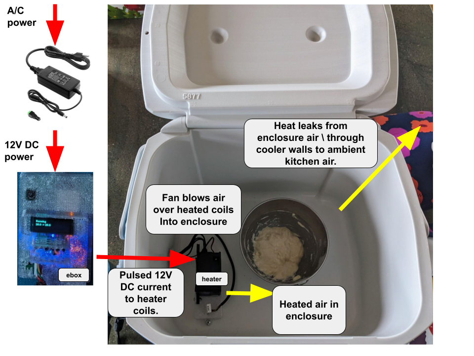
Think of the energy like water flowing through a series of pipes:
- The EBox pumps 12V power into the heater.
- The controller regulates this power using Pulse Width Modulation (PWM),2 flicking the heater on and off so fast that we achieve a precise average power level.
- The heater coils turn that electricity into heat, and a fan forces that warmth into the air inside the cooler.
- Finally, energy flows from the air into the dough (our goal), but it also leaks out through the cooler walls and into the kitchen (our loss).
We can’t sense the dough’s internal temperature directly without sticking a probe into it, but we can sense the enclosure air and the kitchen air. The dough eventually tracks the enclosure temperature.
The System Model: Simplifying Reality
A perfect model would describe every atom in the cooler, but that is impractical. Instead, we use a “lumped model.” We assume that the temperature within each “lump” (like the air volume or the heater coils) is uniform, which lets us describe the entire system with just a few key numbers.
System Variables (What changes)
| Variable value | Symbol | Units | Known? |
|---|---|---|---|
| Electrical power supplied to the heater | W | Partially | |
| Temperature of heater coils | °C | No | |
| Temperature of enclosure air | °C | Yes | |
| Temperature of ambient kitchen air | °C | Yes | |
| Heat flow from coils to the enclosure air | W | No | |
| Heat flow from enclosure to ambient air | W | No |
System Constants (What stays the same)
| Constant value | Symbol | Units |
|---|---|---|
| Thermal capacitance of the heater | J/°C | |
| Effective thermal capacitance of the enclosure | J/°C | |
| Thermal resistance from heater to enclosure air | °C/W | |
| Thermal resistance from enclosure air to ambient air | °C/W |
Think of thermal capacitance as a battery for heat; it tells us how much energy we need to dump into the cooler to raise its temperature by 1°C. Thermal resistance is the insulation; it tells us how hard it is for that energy to escape.
We can visualize the entire system like this:
Investigating the Cooler
If we know how the cooler works, it is much easier to control it. I want to know exactly how much energy it takes to warm up and how well it holds onto heat.
Measuring Thermal Resistance ( )
The rate of heat loss through the walls is proportional to the temperature difference between the inside and outside. At steady state, when the temperature has stopped changing, the power we put in exactly matches the power leaking out.
I used a smart socket to measure the power. Dough133 required 20W of heater power to maintain 36.2°C in an 18.5°C kitchen.
This number tells us that for every 1°C we want to be above the kitchen temperature, we need about 1.14 Watts of continuous power.
Finding the Time Constant ( )
What happens if we turn the heater off? The enclosure will cool down following an exponential decay. The speed of this decay depends on the “time constant” ( ). The greater the time constant, the better the insulation.
I performed an experiment: I heated the cooler and logged the temperature as it returned to room temperature.
The fit is excellent, and the results show a time constant of about 1540 seconds (25:40 minutes): the time for a 63% decay.
Since we already knew the thermal resistance ( ), we can now find the thermal capacitance ( ):
This is much higher than the value for just air, which tells us that the inner walls of the cooler are absorbing and holding a lot of heat.
The Control Strategy: The Plan and the Correction
Now that we have a model, we can build the controller. I chose the traditional two-part strategy: Feedforward3 (The Plan) and Feedback4 (The Correction).
1. Feedforward: Predictive Control
The model tells us exactly how much power is theoretically required to stay at the target temperature. If the kitchen gets 5°C colder, the feedforward component immediately bumps up the power without waiting for the internal sensor to detect a drop.
By collecting data for steady-state power at different PWM commands, I found a nicely linear relationship. This allows the controller to command the necessary power.
2. Feedback: Corrective Control (PID)
Since the world isn’t perfect, we use PID control5 to fix the errors. PID stands for:
- Proportional (P): If we’re 2°C too cold, turn up the heat.
- Integral (I): If we’ve been 0.5°C too cold for ten minutes, slowly increase the power until the error finally vanishes.
- Derivative (D): If the temperature is rising too fast, back off the power to prevent an overshoot.
Handling Actuator Saturation
A common pitfall in control is Integral Windup.
Our heater can’t go below 0% or above 100% power.
If the lid is left open, the Integral term will see a massive error and try to command
500% power.
When the lid finally closes, the controller would stay at full power for way too long,
potentially baking the dough.
My og3 library’s PID logic includes anti-windup to prevent this.
Trajectory control: Being Nice to the Hardware
Another way to help the controller is to avoid asking it to do things it physically can’t. We know our heater has a limit (60W) and the cooler has a capacitance (1750 J/°C). So the fastest we can heat up is about 0.03°C per second. Dough133 limits the target temperature’s rate of change to this value, ensuring the controller stays in its comfortable operating range.
The Final Result: Extreme Control, Happy Yeast
I tuned the gains ( ) by hand while watching the live telemetry from the ESP32. The result is a system that handles most of the load with feedforward, while the feedback loop quietly cleans up the noise.
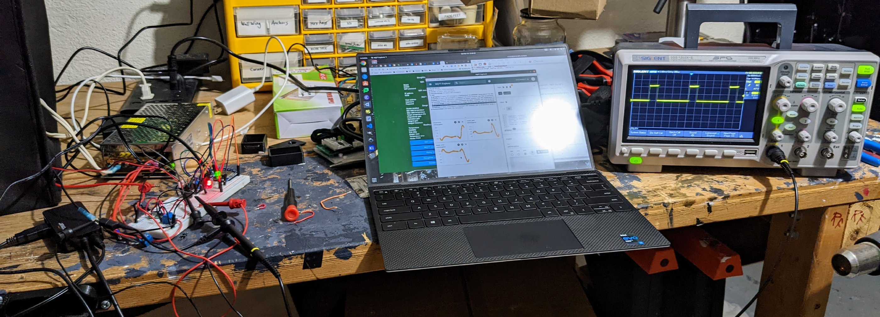
The controller sends a status update every second via MQTT. Here is an example at steady state:
{
  "temp":    26.97,
  "error":   0.03,
  "command": 0.134,
  "ff_cmd":  0.108,
  "p_cmd":   0.009,
  "d_cmd":   0.025,
  "i_cmd":  -0.008
}
Conclusion
By combining a simple thermal model with a PID controller, I transformed a cheap plastic cooler into a precision instrument for proofing sourdough. Could we have gotten by with a constant power heater or even a small lightbulb? Probably. But that would just be boring.
References
-
Control theory is a field of control engineering and applied mathematics that deals with the control of dynamical systems ( Wikipedia ). ↩︎
-
Pulse-width modulation (PWM) is a method of representing a signal as a rectangular wave with a varying duty cycle (ratio of “on” to “off”) ( Wikipedia ). ↩︎
-
In control engineering, a Feedforward Control System is a control system that uses sensors to detect disturbances affecting the system and then applies an additional input to minimize the effect of the disturbance. This requires a mathematical model of the system so that the effect of disturbances can be properly predicted ( Wikipedia ). ↩︎
-
Feedback Control: In the case of linear feedback systems, a control loop including sensors, control algorithms, and actuators is arranged in an attempt to regulate a variable at a setpoint ( Wikipedia ). ↩︎
-
A proportional–integral–derivative controller (PID controller or three-term controller) is a feedback-based control loop mechanism commonly used to manage machines and processes that require continuous control and automatic adjustment ( Wikipedia ). ↩︎