Dough133 Electronics: Fail-Safe ESP32 PCB Design for Heater Control
Posted on March 17, 2024 • Last modified on August 20, 2026 • 11 min read • 2,298 words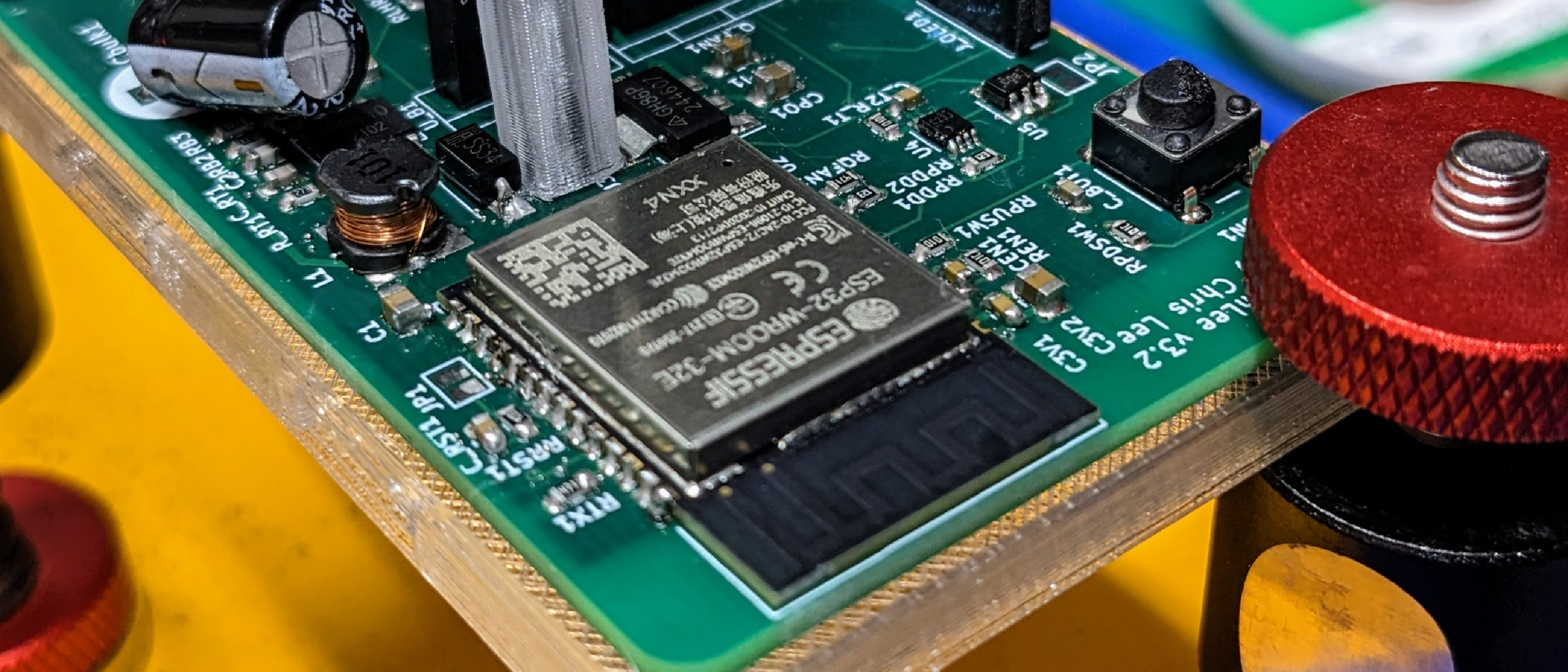
Introduction
Following up on the Dough133 sourdough proofer overview, this post covers the custom ESP32 controller board mounted to the side of the cooler: basic circuit design, PCB layout, and an essential hardware safety mechanism.
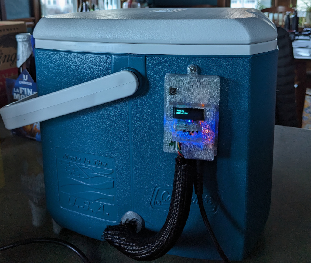
During early testing, the microcontroller locked up mid-run and left the heater at full, unregulated power. While the PTC heater has internal safety limits, the insulated cooler quietly climbed to 50°C (120°F) and stayed there until I manually cut power. Relying purely on software to manage a heating element is a safety hazard. I wanted a hardware-level guarantee that power is cut if the microcontroller ever halts.
The Failure and the Hardware Interlock
I don’t know the exact reason the prototype halted. Possibly a loose sensor connection hung the I2C bus, or the runtime encountered an unhandled exception. This problem happened with an early ESP8266 version of the system. Whatever the cause, the lesson was clear: heater power requires active proof of life from the microcontroller.
To solve this, I designed a hardware heartbeat interlock. The microcontroller software must continuously toggle a dedicated digital output pin at a specific frequency to prove it is executing properly. If the microcontroller halts, leaving the pin stuck either high or low, the hardware must automatically disconnect power from the heater.
A search for hardware heartbeat monitors pointed me toward a classic solution: a missing pulse detector1 circuit. I implemented one using a SN74LVC1G123D Monostable Multivibrator2 IC configured to hold its output high only as long as input pulses arrive at 100 Hz or faster.
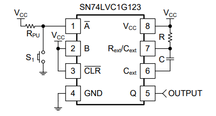
The timing diagram below from the data sheet indicates that if we have , a resistor with value , and use a capacitor of , then the circuit should produce an output pulse with a duration after each rising edge (a signal transitioning from low to high) is seen on its input.
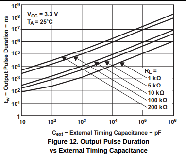
If we provide an input signal of more than , these output pulses will run together and the output just stays high. If the input pulses stop and the signal stays locked high or low, then the output will go low in and stay there.
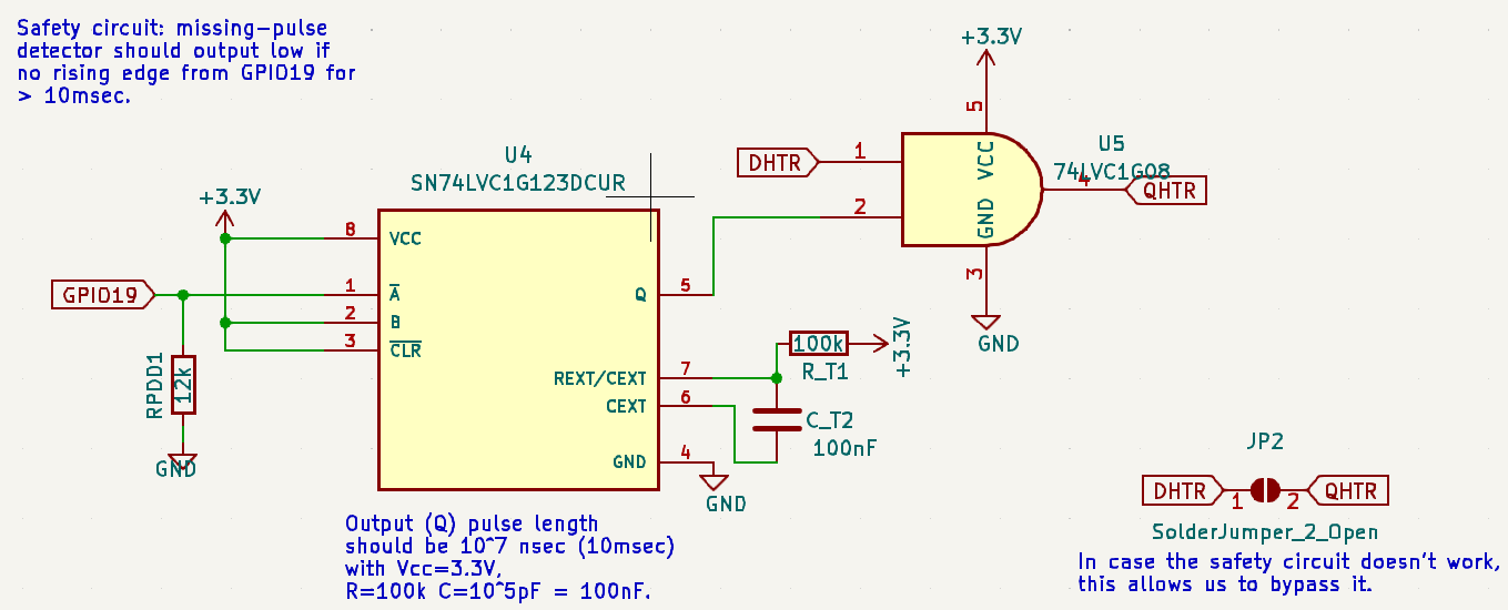
The portion of the circuit design for the safety circuit is shown above.
The output of the missing pulse detector is combined via an AND gate with the PWM
control signal for the heater.
Thus the PWM signal DHTR is transmitted to the MOSFET via QHTR only if rising edges
also arrive from output pin GPIO19 of the ESP323 microprocessor at a high enough rate.
If the microprocessor locks up or software is not running properly to generate the
heartbeat signal, power to the heater is quickly cut off.
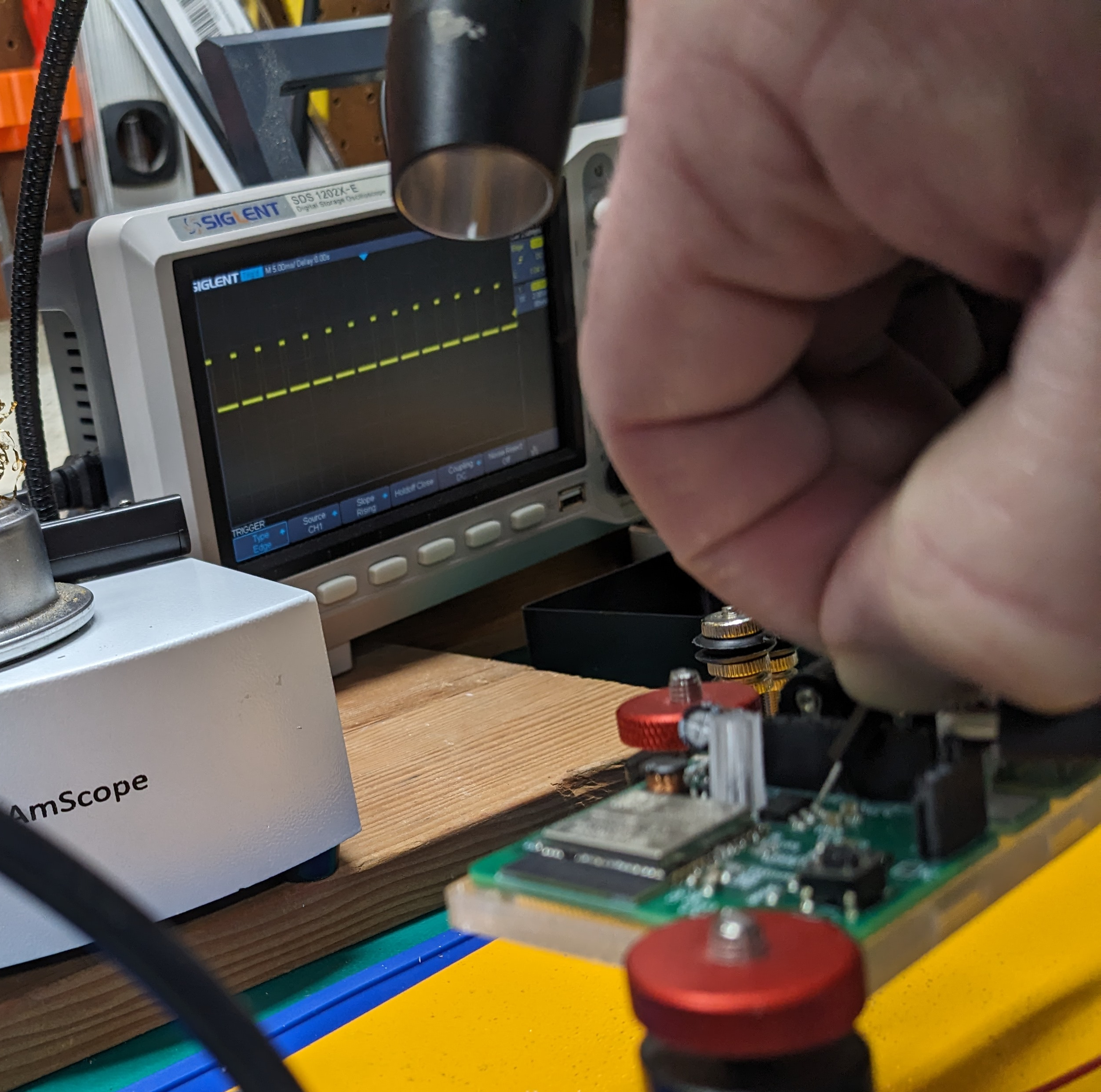
It worked! I tested with a 50Hz input and saw a 50% duty cycle on the output. That demonstrates a 10 msec high output on each rising edge, as expected, followed by a 10 msec low output.
Precision Heater Control with PWM and Simple Fan Control
It is not really necessary to control the temperature of the Dough133 enclosure with extreme precision. As long as we have good sensors and control hardware, however, precise control is far more satisfying (for details, see Dough133 Control: Precision ESP32 PID and Feedforward Temperature Control ). To closely control the temperature, we need incremental control over the power provided to the heater. We cannot just run the heater like a steam furnace: at either full power or no power. A common way to gain this kind of incremental control is to use a MOSFET,4 a component that allows quickly switching power between full-on and full-off, in combination with pulse-width modulation (PWM).5 PWM is performed by rapidly cycling the power on and off, but varying the proportion of time it is on verses off. This way we can precisely control the proportion of total available power that is provided to the heater.
Fan power control uses the same hardware but is controlled more simply, without PWM. The MOSFET is just used as a switch: setting the fan full-on when heat control is active, and full-off 90 seconds after heat control stops. This delay helps ensure the heater coils are cooled.
A flyback diode6 is used alongside each MOSFET. A diode is a component which allows current to flow in one direction but not the other. The figure below is a circuit diagram of a simple circuit with an inductance and a flyback diode . The resistor represents the resistance of the inductor’s windings
A flyback diode acts a bit like the “freewheel"mechanism on a bicycle. Unless you have a “fixie” bike where the pedals are rigidly connected to the wheels, when you stop pedaling the freewheel mechanism allows the bike to coast. If you are biking quickly and try to stop too suddenly, your momentum will tend to make bad things happen (flying over the handlebars, bent bike frames, etc…). Similarly, current through a coil has a kind of momentum caused by “inductance” which is like the mass of you and your bike. Suddenly giving the current nowhere to flow is like trying to make your bike stop instantly when you stop pedaling. The flyback diode acts like the freewheel mechanism: it lets current circulate through the heater coils or fan motor until the resistance of the coils converts this electrical energy into heat. Pushing current through the motor or heater is like biking uphill. When the MOSFET is on, it is “pedaling the bike.” When it turns off, the diode lets the electrical current “coast” and slow gradually.
Microprocessor Selection: ESP8266 vs ESP32
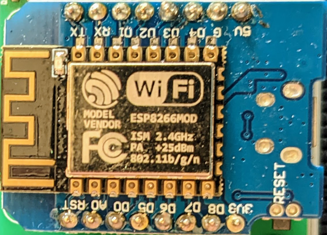
Earlier versions of the system were controlled using a Wemos Mini microcontroller, powered by the ESP8266.7
I’ve since shifted to using its successor, the ESP32,3 in my designs. So later versions now use an ESP32 WROOM module soldered onto the device PCB.
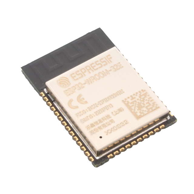
Both of these microcontrollers are inexpensive, relatively powerful, have many digital i/o pins for communicating with sensors and other devices, and support built-in WiFi. They also have an extensive ecosystem of open source libraries and are easy to program.
Power Supply Design
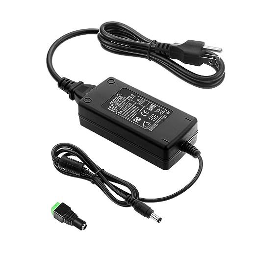
The heater and fan both require 12V power. The main power supply for the device is a 12V A/C adapter8 often used with LED light banks. The PCB incorporates a buck converter9 to efficiently convert the 12V power to 5V. This is a BD90610UEFJ-C.10 5V power is supplied to the OLED and enclosure’s SHTC3 module. An LDO voltage regulator11 converts 5V to 3.3V. The microcontroller and most other components use 3.3V power.
PCB Design with KiCad
This is one of the first PCBs I designed. I’m learning about PCB design by iterating my designs and reading blogs and following some YouTube channels, but I’m self-taught and likely am doing some basic things wrong. So take my design with a grain of salt, defer to the real experts, and please post suggestions if you have them. That said, my boards do basically work, so that is something at least.
Design Evolution: From Breadboard to Custom PCB
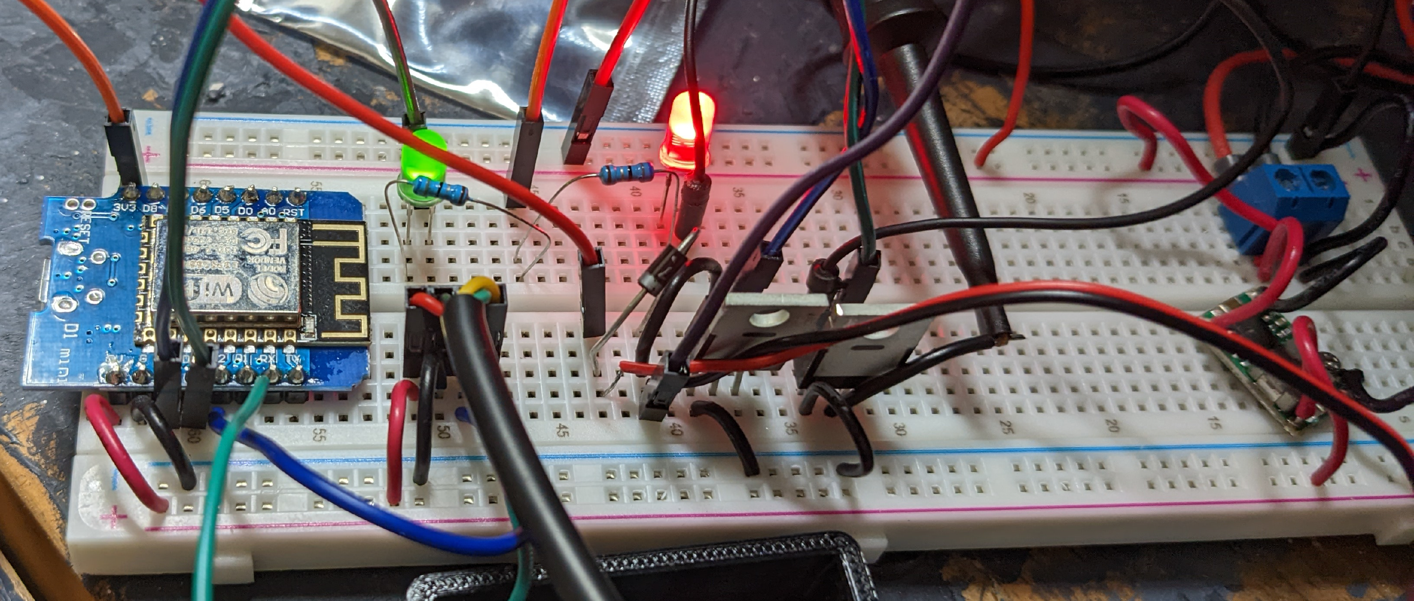
Here is the initial breadboard circuit I built while learning how to control the heater using PWM. This used a Wemos D1 Mini clone microprocessor module, based on the ESP8266, for control.
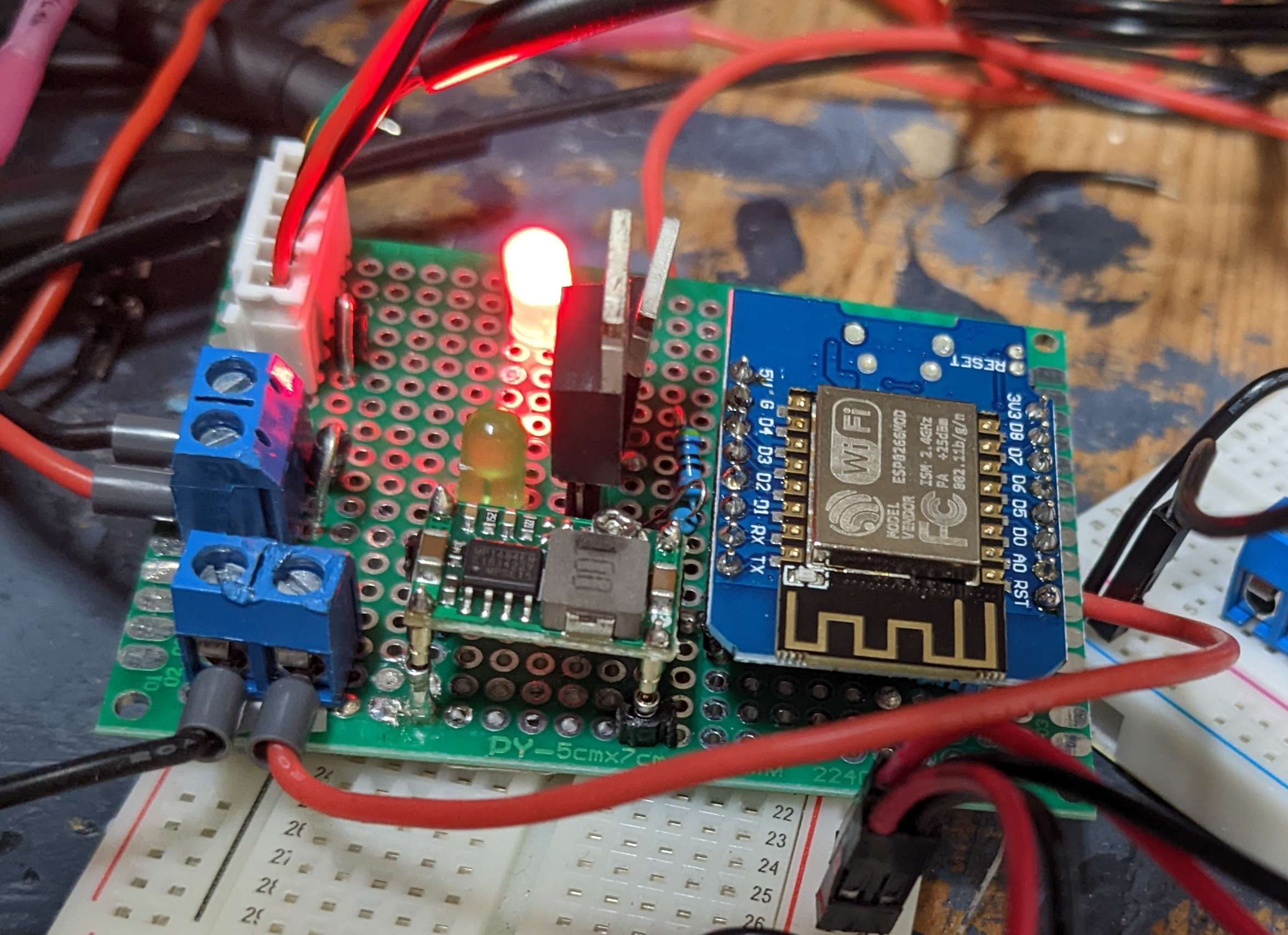
Later, I designed and ordered a printed-circuit board (PCB) implementation of the design. I use KiCAD12 to design the PCBs and order them from JLCPCB.13 I was still using through-hole components14 at this stage. The PCB was an easier, more reliable replacement for the soldered perfboard.
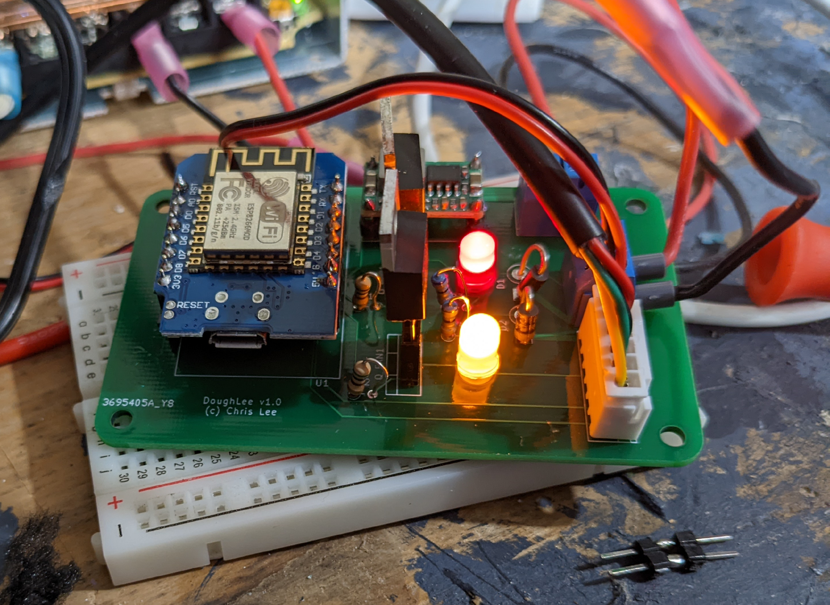
Both the perfboard and early PCB use an integrated buck converter module purchased separately to generate 5V power from the 12V supply. The Wemos d1 mini clone board has an integrated LDO converter to generate 3.3V from the 5V power.
“Modern” PCB Layout with Surface Mount Components
My later PCB versions are based on the newer ESP32 microprocessor, and mostly use surface-mount components. The buck converter and LDO voltage regulator are part of the PCB, along with the safety circuit.
Here is a map of the component layout on a recent PCB.
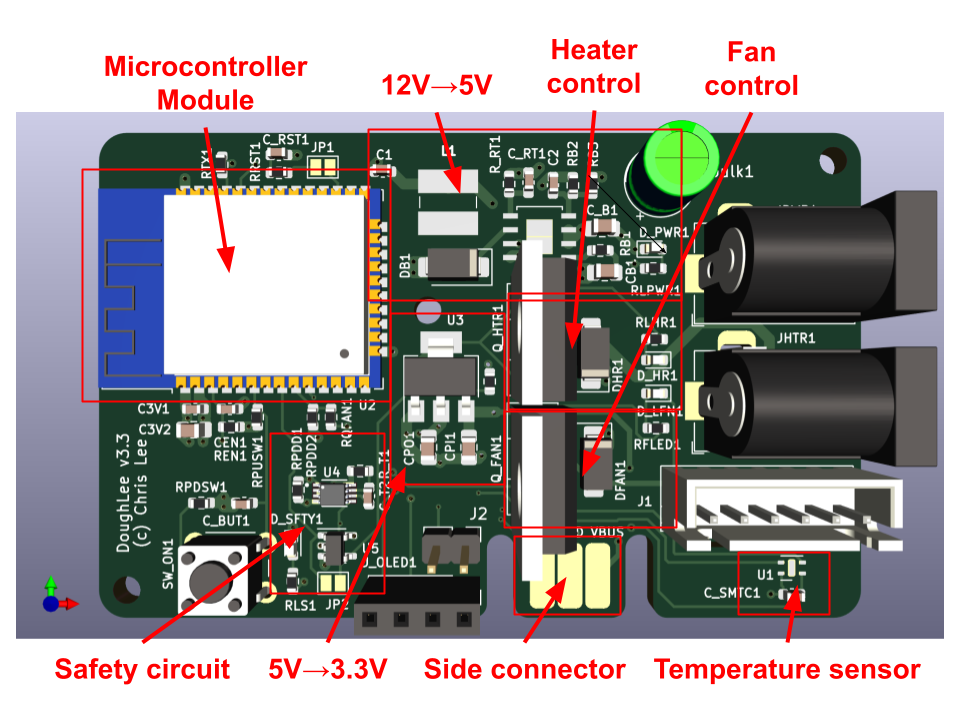
The side-connector is a way to power and communicate with the board, for programming and debugging via a serial monitor, without incorporating a USB-to-serial chip and related components directly on the board. I built a separate device which can attach to any board with this edge connector and interface with USB.
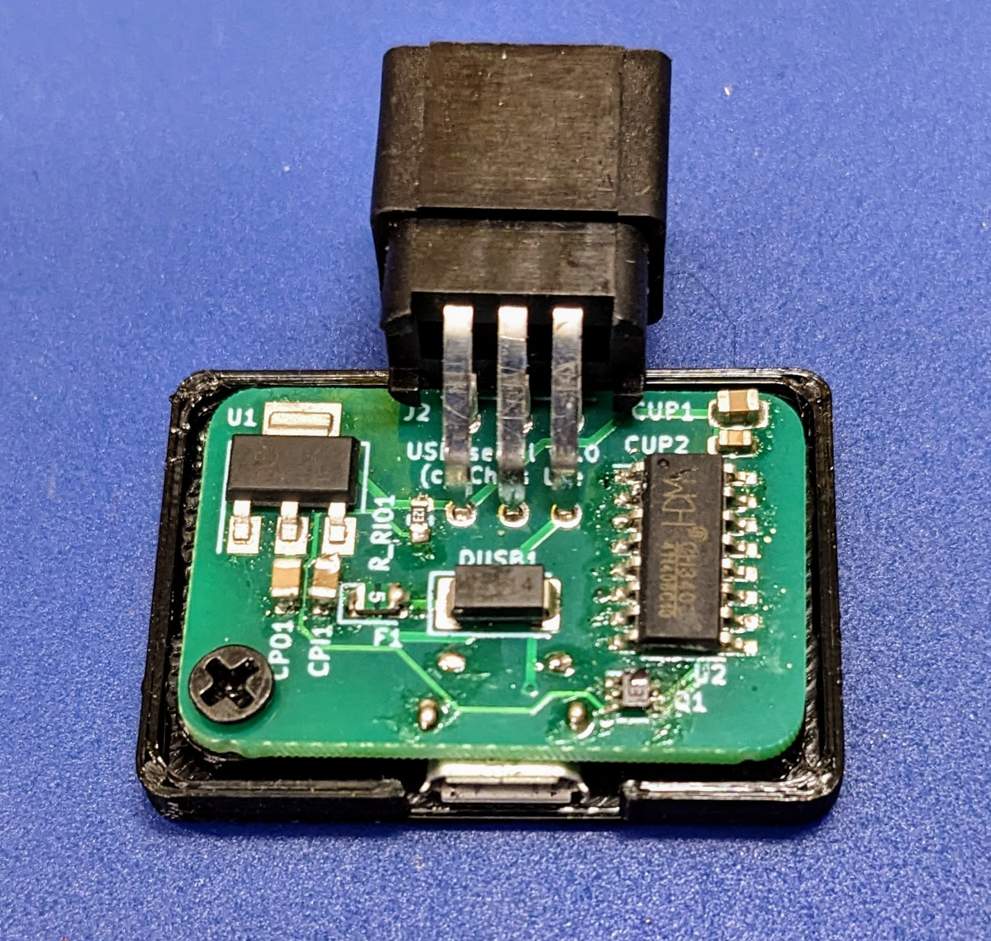
I use this same connector and device for a number of my PCB designs.
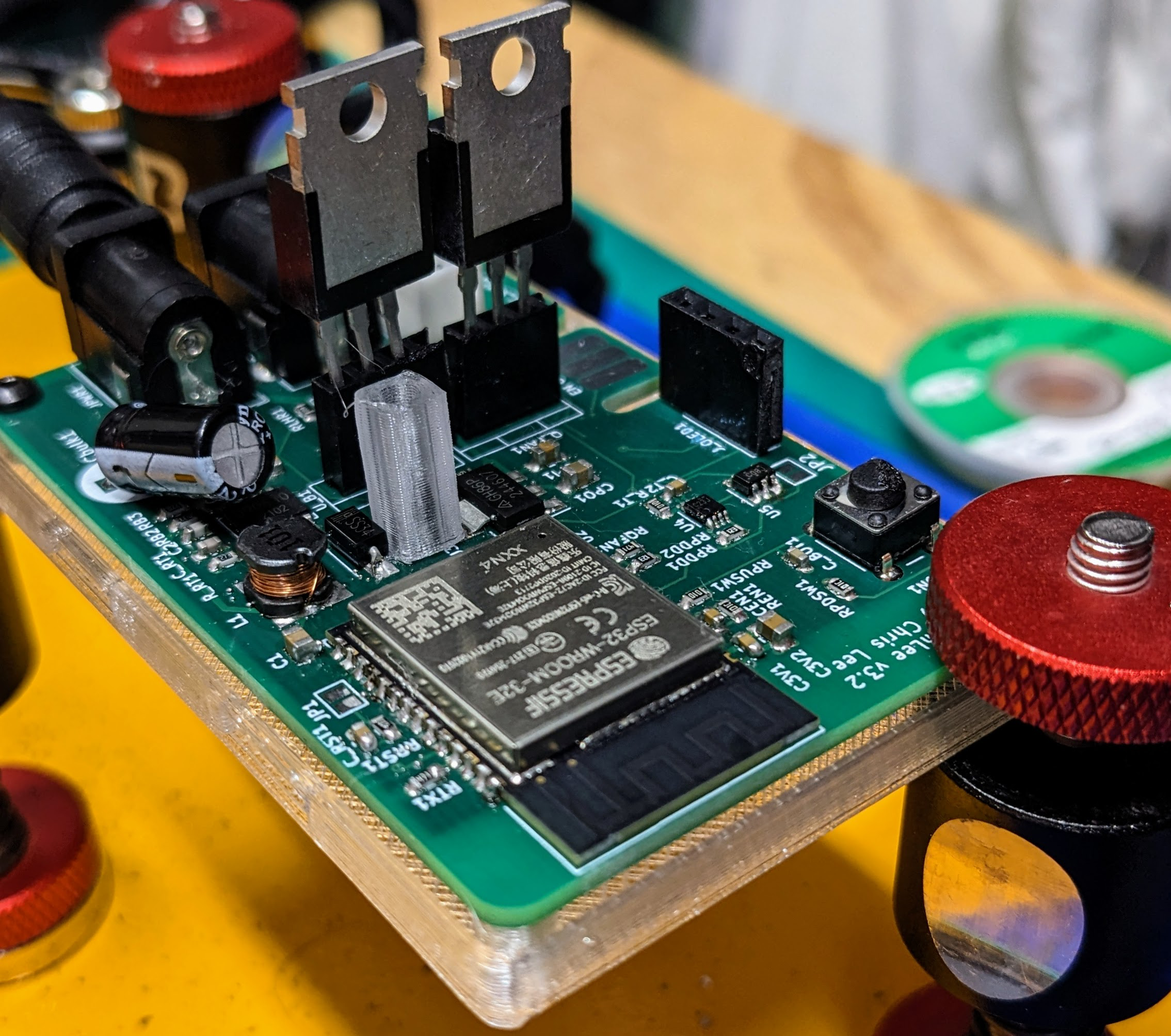
Here is a view of the assembled PCB.
Managing MOSFET Heat
As an electronics newbie, one thing I am uncertain about is how to handle heat from the MOSFETS, which are the two large components sticking up from the middle of the board. I attached these via DuPont headers to make them easy to replace, and which somewhat thermally isolates them from the rest of the board. The heater’s MOSFET gets hot to the touch when the heater is at full power. However, the enclosure gets up to temperature quickly, and then the power sent to the heater is quickly reduced, so the MOSFET isn’t this hot for very long.
I could potentially attach a heat sink to the MOSFETs, or I could attach them to a large metal object to drain heat if one was nearby. Nearly everything near the EBox is plastic, however. For now, I just designed the EBox with air holes around the MOSFETs for cooling and this seems to be OK.
Troubleshooting and Repairs
There are two main problems with the current board. The first is that the onboard SHTC3 sensor is not talking to the microprocessor. I might have done a poor job soldering the tiny component to the PCB (it is tiny), it could be a software problem, or it might be due to some problem with the PCB design (update: I think it was missing pull-up resistors on the I2C bus). I’ll try to assemble the next version of the board and try again before attempting further debugging.
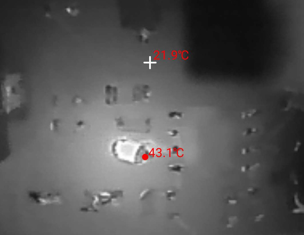
The second problem was the failure of a small capacitor on one board. This was a small 0805 capacitor near the input of the boost converter IC. I think I was using a component with appropriate specifications, but I could have done something wrong. This was also a cheap component from a big generic assortment ordered from AliExpress, rather than from a more traceable source like Digikey. I identified the failed component using my IR camera: the short across the component caused it to get much hotter than the rest of the board. Upon replacing the capacitor, the board worked again.
Conclusion
I’m not an electrical engineer, so I expect there are problems with this design easily noticed by the non-novice, or at least obvious ways to improve it. I’m still learning: please let me know what I could do better! Nevertheless, the system basically works as intended and it has been a fun learning experience to iterate through the design a few times.
For details on the firmware PID and feedforward control algorithms, see Dough133 Control , and for step-by-step physical assembly, see Dough133 Assembly .
References
-
Missing pulse circuit found at this forum post . ↩︎
-
SN74LVC1G123D Monostable Multivibrator IC ( DigiKey , data sheet ). ↩︎
-
ESP32 : a family of microcontrollers made by Espressif Systems, and the successor to the ESP8266 microcontroller. ↩︎ ↩︎
-
MOSFET. The metal–oxide–semiconductor field-effect transistor (MOSFET) has the ability to change conductivity with the amount of applied voltage, and can be used for amplifying or switching electronic signals ( Wikipedia ). ↩︎
-
Pulse-width modulation (PWM) is a method of representing a signal as a rectangular wave with a varying duty cycle (ratio of “on” to “off”) ( Wikipedia ). ↩︎
-
A flyback diode is any diode connected across an inductor used to eliminate flyback, which is the sudden voltage spike seen across an inductive load when its supply current is suddenly reduced or interrupted. It is used in circuits in which inductive loads are controlled by switches, and in switching power supplies and inverters ( Wikipedia ). ↩︎
-
ESP8266 : a low-cost Wi-Fi microchip, with built-in TCP/IP networking software, and microcontroller capability, produced by Espressif Systems. ↩︎
-
A buck converter is a DC-to-DC converter which decreases voltage, while increasing current, from its input (supply) to its output (load). It is a class of switched-mode power supply ( Wikipedia ). ↩︎
-
A low-dropout regulator (LDO regulator) is a DC linear voltage regulator that can operate even when the supply voltage is very close to the output voltage ( Wikipedia ). ↩︎
-
JLCPCB is a company from which I ordered circuit boards designed using KiCAD. ↩︎
-
Through-hole technology is a manufacturing scheme in which leads on the components are inserted through holes drilled in printed circuit boards (PCB) and soldered to pads on the opposite side ( Wikipedia ). ↩︎