Modernizing My Base ESP32 PCB Design: Native USB-C, ESP32-S3, and Thermal Isolation
Posted on October 4, 2026 • Last modified on October 10, 2026 • 11 min read • 2,190 words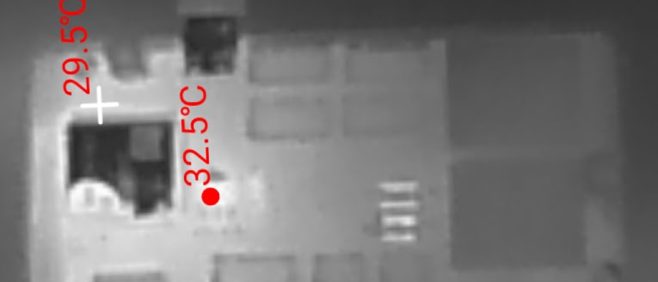
Introduction: Modernizing a Shared IoT Platform
Across my home automation projects, my custom sensor boards share common purposes. I make devices that track the state of different aspects of my home and yard, and sometimes perform actions based on this information. They generally interface with Home Assistant via the MQTT protocol over WiFi.
Unsurprisingly, these boards evolved to include a set of shared subsystems for power, computation, and serial communication. The shared subsystems are reliable and inexpensive, and use a common set of components that are easy to keep in stock.
But occasionally, subsystems like these need to be reconsidered. After having some trouble with a micro-USB connector on my Garage133 board and watching a video that listed micro-USB jacks as one of the “10 Components You Should NEVER Use in a Product” , I decided it was time to update my designs to use USB-C. At the same time, since modern ESP32 modules now offer built-in USB support, I thought it was also time to switch to native USB rather than relying on a USB-to-UART bridge on a separate daughterboard.
This post describes:
- Modernizing the platform with native USB-C and the ESP32-S3, and
- Improving thermal isolation for SHTC31 temperature and humidity sensors.
This post is sponsored by PCBWay . They generously supplied two revisions of the Plant133 and Garage133 PCBs as I worked through the changes to my base design with USB-C. As usual, the boards were easy to order, arrived quickly, look great, and work reliably.
The Old System: Micro-USB and Edge Connector
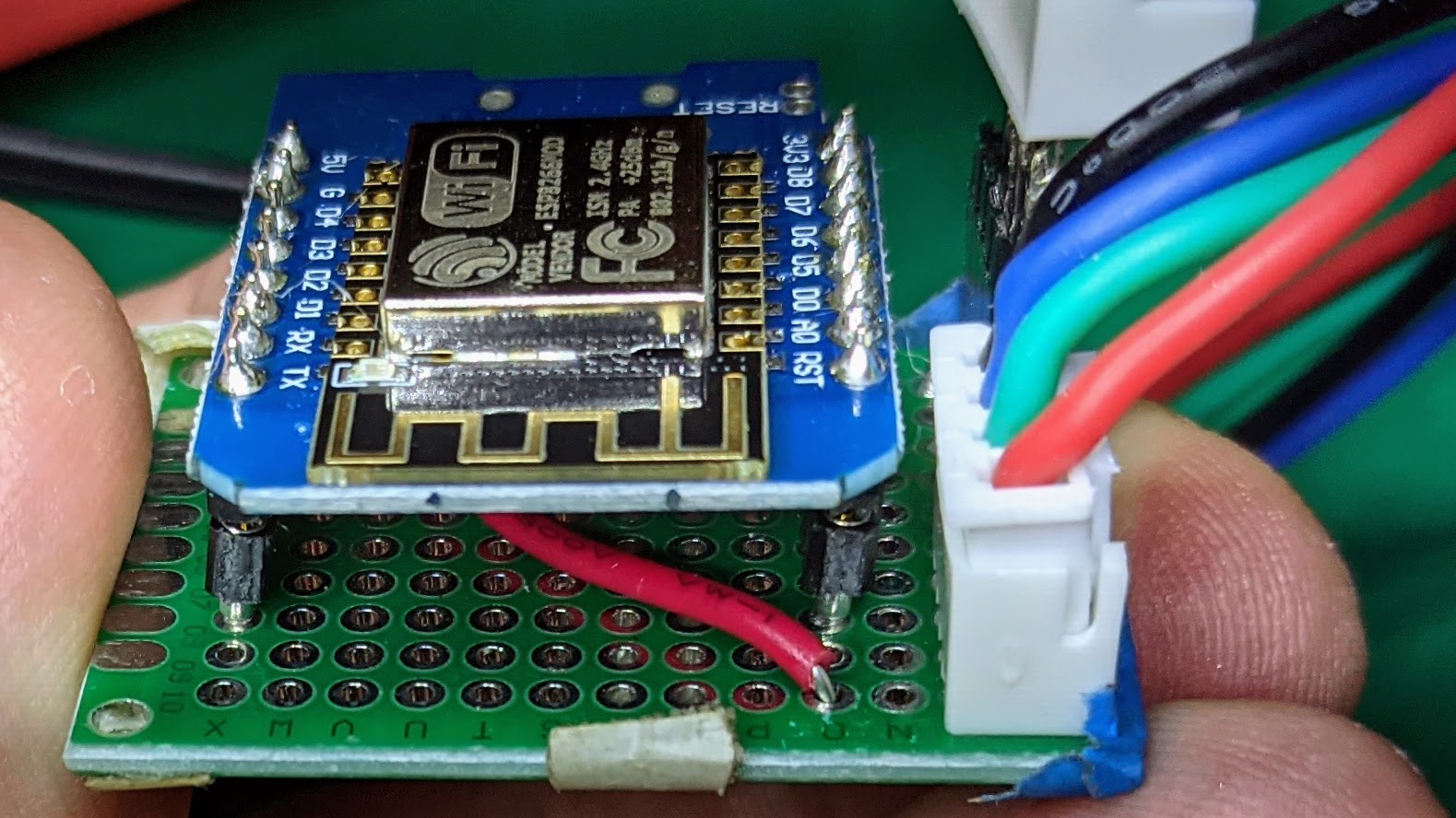
My first ESP-based projects were built around Wemos D1 Mini devboards, based on the ESP82662. Devboards like the Wemos Mini include a 3.3V power supply and USB interface, as well as through-holes that are easy to connect to or solder headers to. The USB connection supplies power to the board, allows programming the microcontroller, and enables serial communication for monitoring and debugging. To connect the ESP8266 to sensors and other devices, I either soldered wires directly to the devboard or added headers to mount it on a breadboard or perfboard.
I am not great at making perfboards, so I decided to teach myself KiCad3 and order my first printed circuit boards. My first PCBs were a direct replacement for perfboards: they included female headers to mount a Wemos Mini devboard.
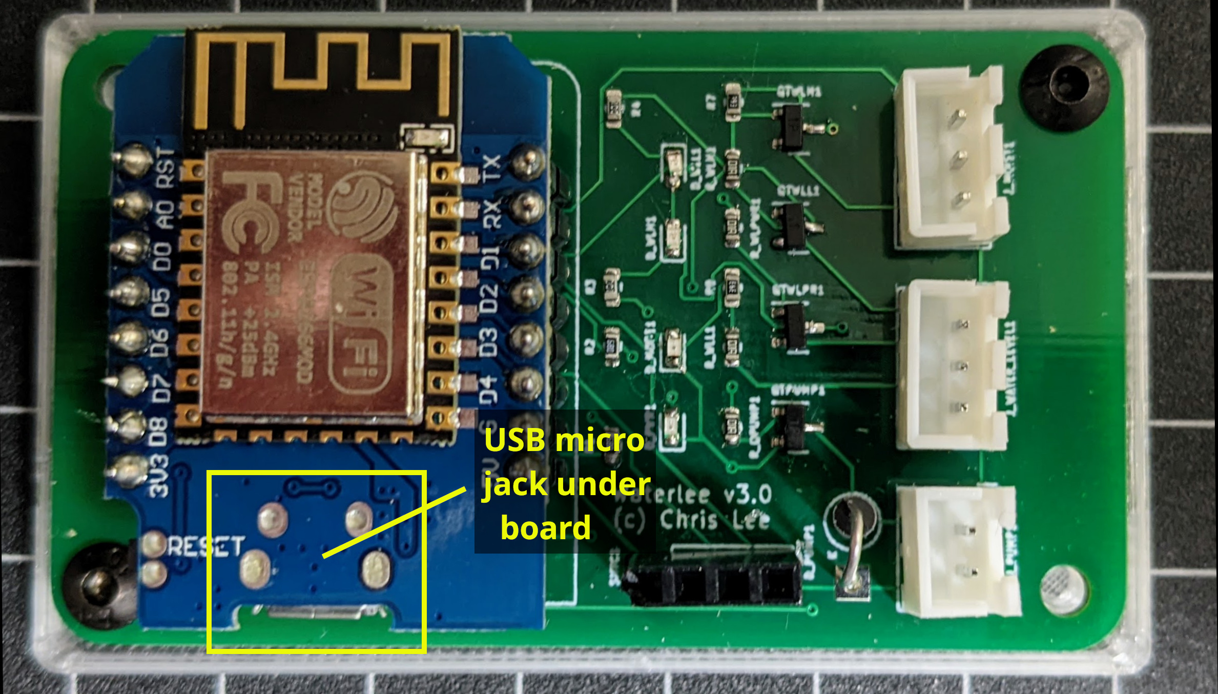
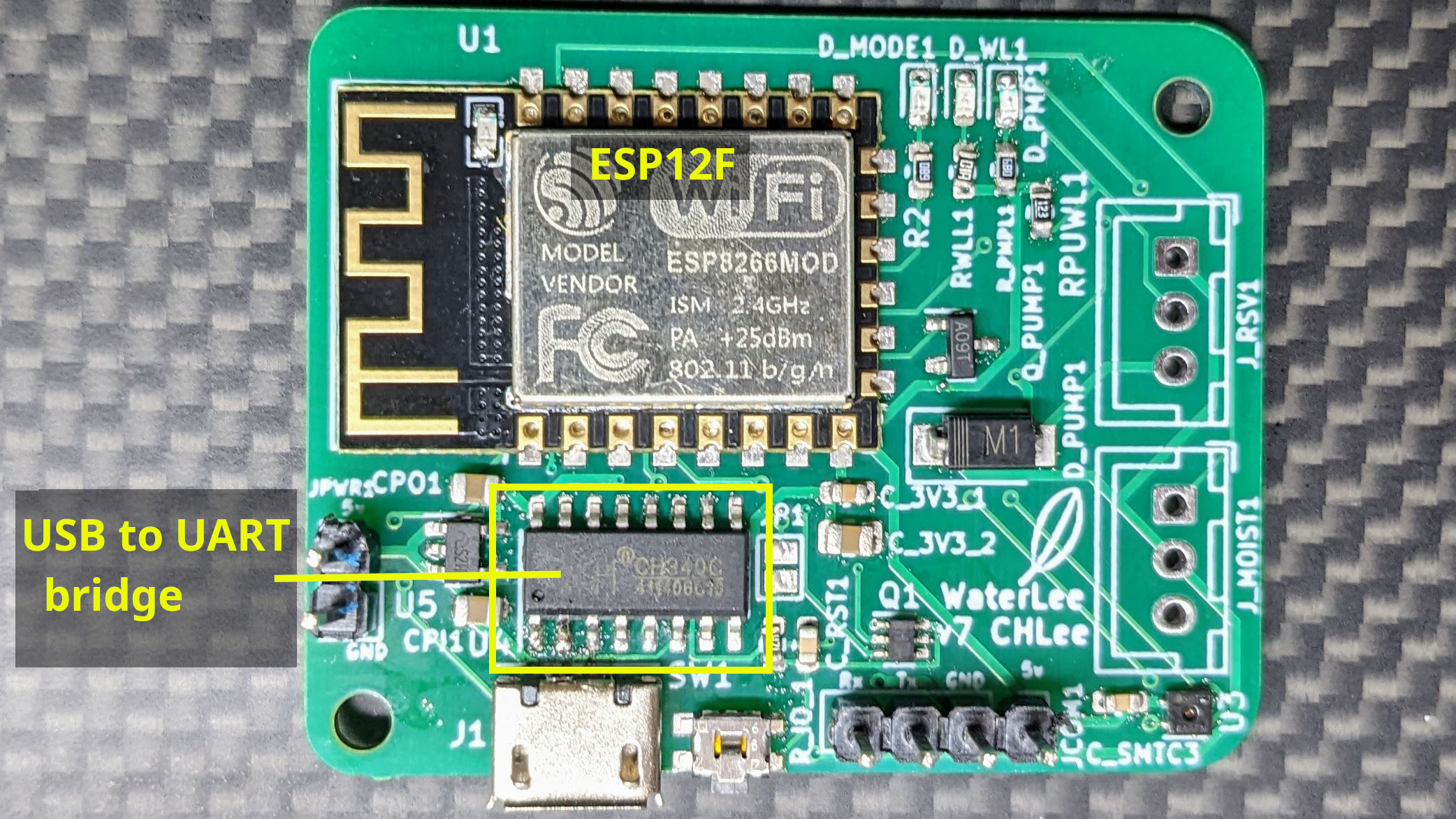
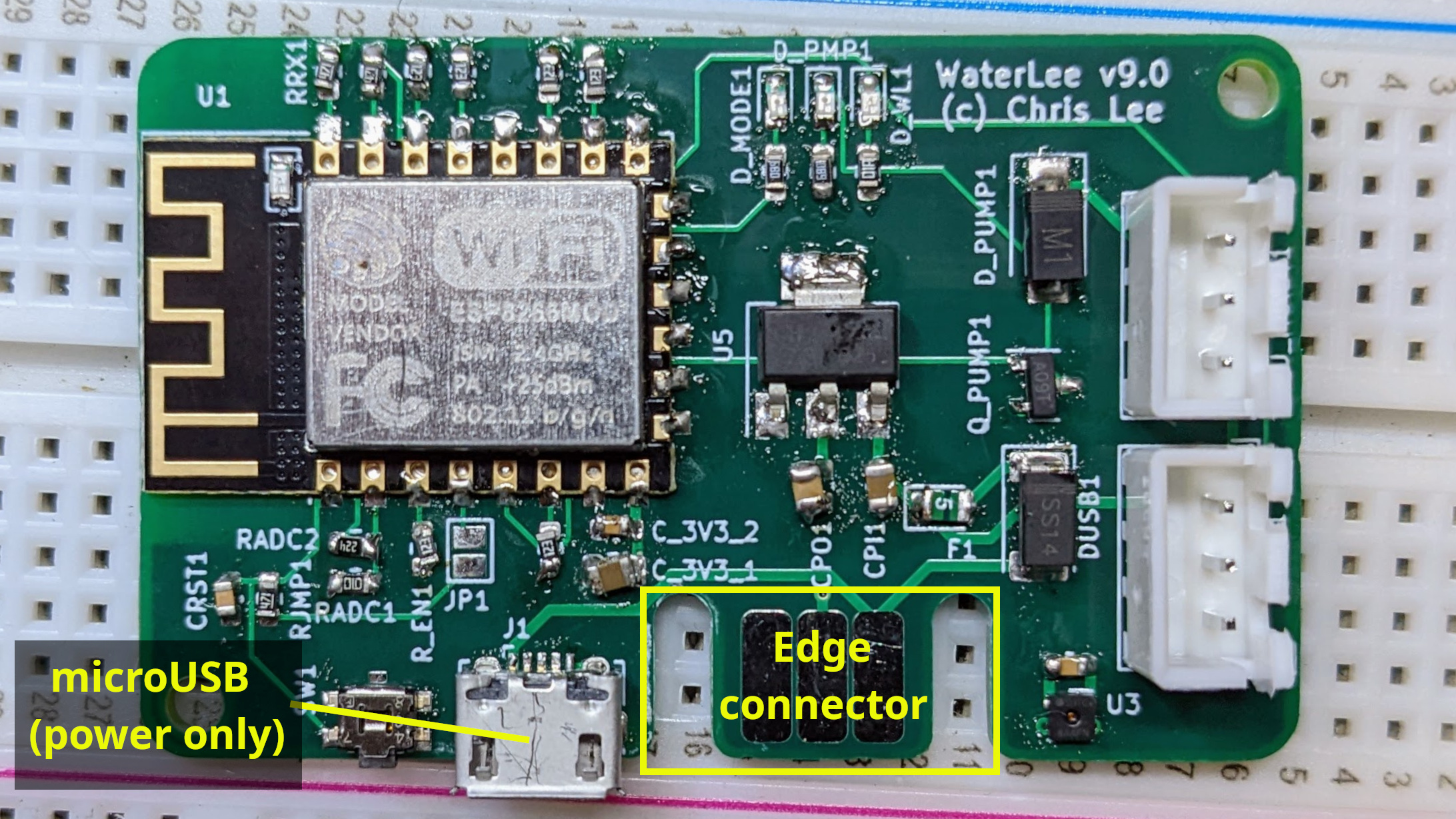
Later PCBs replaced the devboards with an ESP8266 module (an ESP-12F). These PCBs took over the jobs of supplying 3.3V power and the USB interface. For USB communication, necessary for programming and debugging the ESP8266, I integrated a USB-to-UART bridge (CH340C4). A dual NPN digital transistor pair (UMH3N) automatically controlled the ESP8266’s GPIO0 and RST pins for flashing new code (see for example this ESP8266 Programmer Board design ).
The CH340C and dual transistor chips took up board space and were tedious to solder by hand. I found a mention online from someone who made a separate board, connected via an edge connector, to perform this function. I built my own version and created a custom edge-connection footprint to include across my PCB designs.
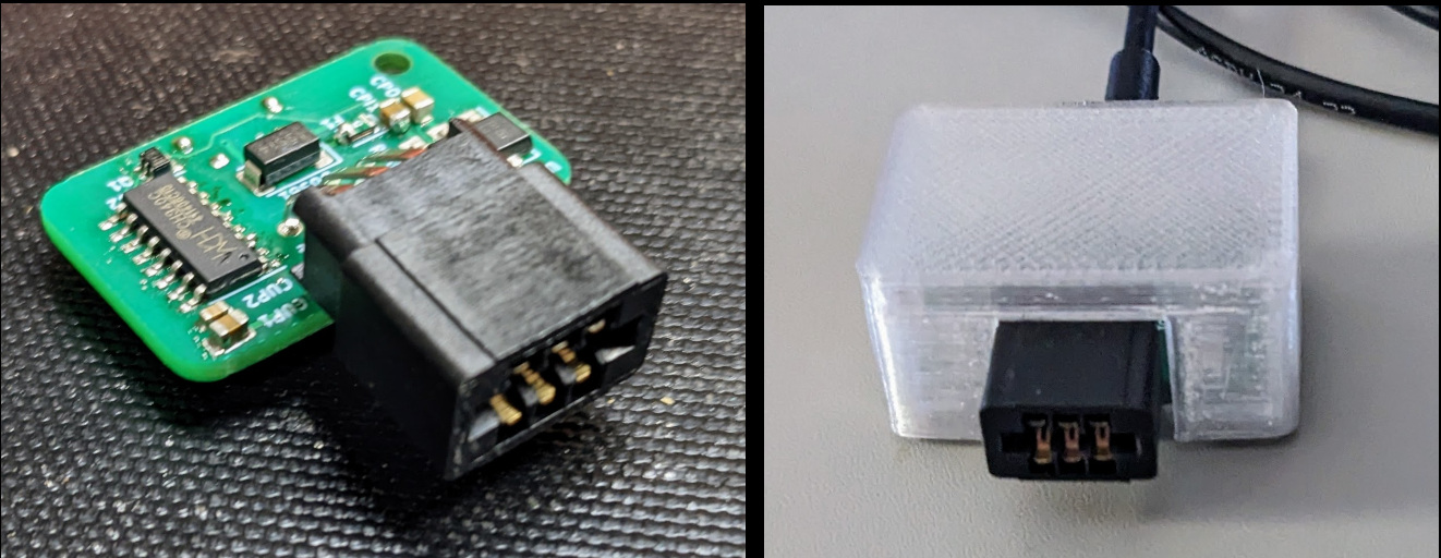
My daughterboard connects via a 6-conductor edge connector which supplies 5V, ground, RX, TX, GPIO0, and RST signals. The same daughterboard handles USB-to-UART conversion and serial communication for all my boards, so individual PCBs do not require their own CH340C or UMH3N chips. This system simplified my PCBs, reduced assembly time, and lowered component costs. The main PCBs still included a micro-USB jack, but strictly to supply 5V power.
The daughterboard was usually needed only to flash the initial firmware onto the device. After that, Over-The-Air (OTA) updates over Wi-Fi handled subsequent firmware revisions.
When I upgraded to the ESP325-WROOM32D module in place of the ESP8266, it also required a USB-to-UART adapter. I kept the same daughterboard system for these newer boards.
There were, however, several downsides to the edge-connector approach:
- Specialized hardware (the custom daughterboard) is necessary to program the boards. You cannot simply plug in an off-the-shelf cable.
- Connecting to a board for serial debugging requires direct physical access to the edge pads. This means disconnecting all external wiring, opening the enclosure, and unscrewing the PCB to rotate it out of the case base so the edge connector is exposed.
- The connection to the edge pads can be finicky, often requiring manual adjustments to seat reliably.
- The daughterboard used a micro-USB jack while my laptop has USB-C ports, requiring a daisy chain of a USB hub, a USB-A to micro-USB cable, the daughterboard, and the edge connector.
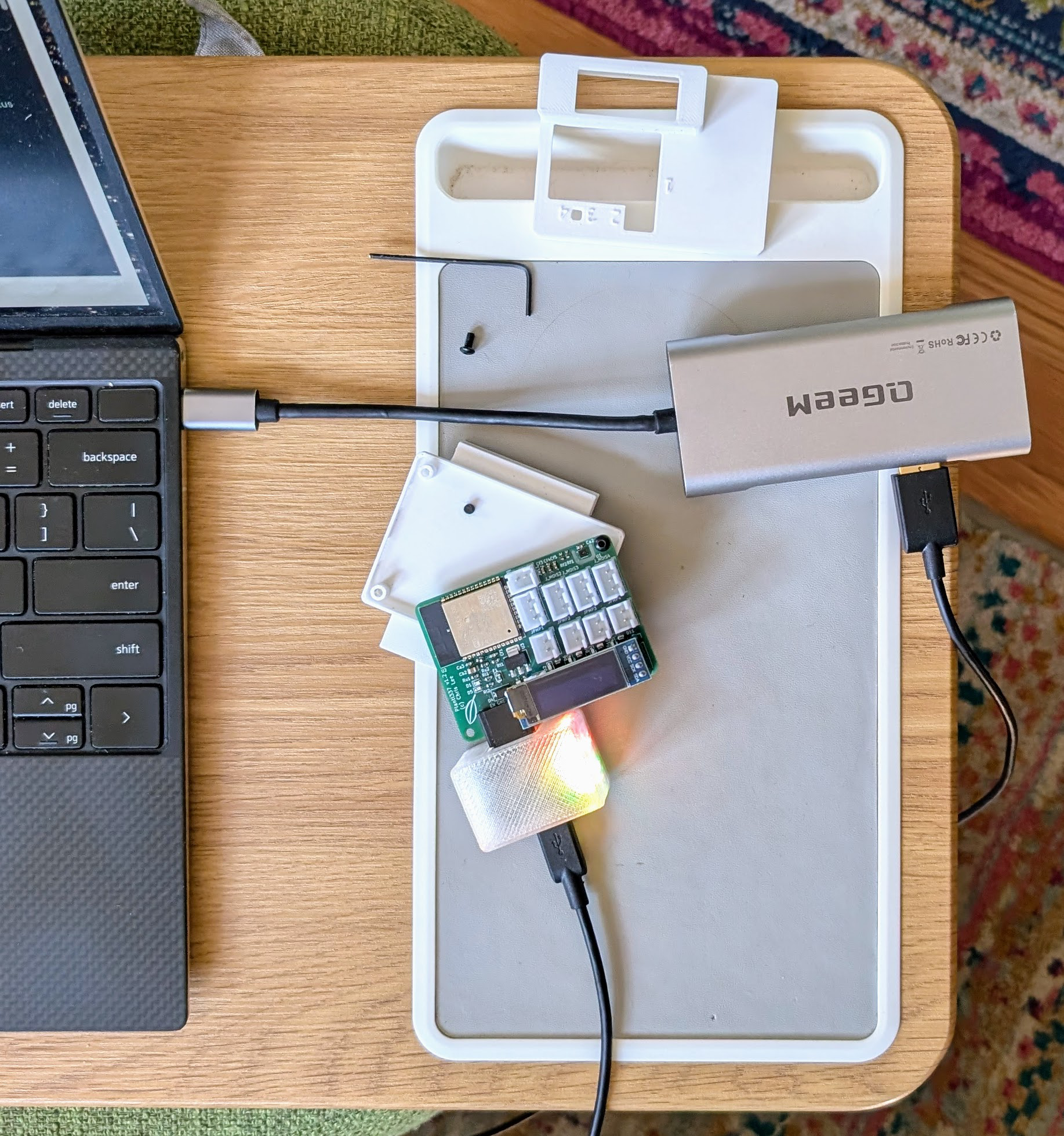
The New System: ESP32-S3 and USB-C
The new approach allows me to connect my laptop directly to my boards with a standard USB-C cable, providing power and serial communication through a single jack. Switching from micro-USB to USB-C offers several key advantages:
- It is more mechanically robust, providing a stronger and more durable socket that improves power reliability.
- It is ubiquitous, making it trivial to find cables and power supplies anywhere in the house.
- It provides a modern, clean finish. Designs with micro-USB feel increasingly dated and look like early prototypes.
Routing serial communication through the exposed external jack means I no longer need to open the enclosure to debug the device. Sensors and power wiring can remain connected while pulling real-time serial logs. If the bootloader pins are also accessible through the case, firmware can be updated without opening the enclosure.

Modern ESP32 modules such as the ESP32-S3 include native USB support directly on the silicon: no external USB-to-UART interface chip is required. These modules are now comparable in price to the older ESP32-WROOM32D, while delivering upgraded processing capabilities (dual-core Xtensa LX7, vector extensions, and improved peripheral multiplexing).
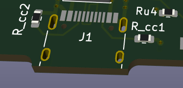
Different USB-C receptacles feature different pin counts. Jacks with a 12-pin or 16-pin footprint support USB 2.0 and power delivery while being much easier to route and hand-solder than full 24-pin USB 3.x connectors. The traces for the D+ and D- data lines to the ESP32-S3 should be routed as a differential pair in KiCad to keep trace lengths matched and maintain impedance. Because USB-C cables are reversible, the receptacle provides two D+ pins (A6/B6) and two D- pins (A7/B7); tie the respective pairs together on the PCB so communication functions in either cable orientation.
To enable proper power delivery from modern USB-C chargers and C-to-C cables, pins CC1 and CC2 must each be pulled down to ground through an independent 5.1 kΩ resistor. A frequent trap in hobbyist designs is tying CC1 and CC2 together to a single 5.1 kΩ resistor, or omitting them entirely. E-marked cables and smart USB-PD power supplies detect connected devices by sensing distinct pull-downs on the CC lines; if they are tied together or left floating, the charger will not supply 5V power.
Because the pin pitch on surface-mount USB-C receptacles is relatively fine, solder bridges can easily form between adjacent pins during reflow. I use a microscope and a multimeter to inspect these pins after the board comes out of the reflow oven, clearing any bridges with a fine soldering iron tip and flux.
To prevent thick cable overmolding from colliding with the 3D-printed enclosure wall before the plug fully latches, the USB-C jack must sit nearly flush with the case exterior. I extend the jack overhang past the PCB edge to bridge the wall thickness of the enclosure.
With native USB on the ESP32-S3, esptool can automatically reset the chip into download mode
over USB CDC control signals, eliminating the need for the discrete RTS/DTR transistor circuit.
However, if firmware crashes, hangs in an early boot loop, or disables the USB peripheral, the
software-based auto-reset will fail.
For this reason, physical pushbuttons for “BOOT” (GPIO0) and “EN” (reset) remain essential
hardware fallbacks.
Holding BOOT while pulsing EN forces the ESP32-S3 into its ROM bootloader, allowing recovery under
any circumstance.
I exposed the EN switch through the enclosure on the latest Plant133 revision so the device can
easily be rebooted without unplugging cables or taking apart the case.
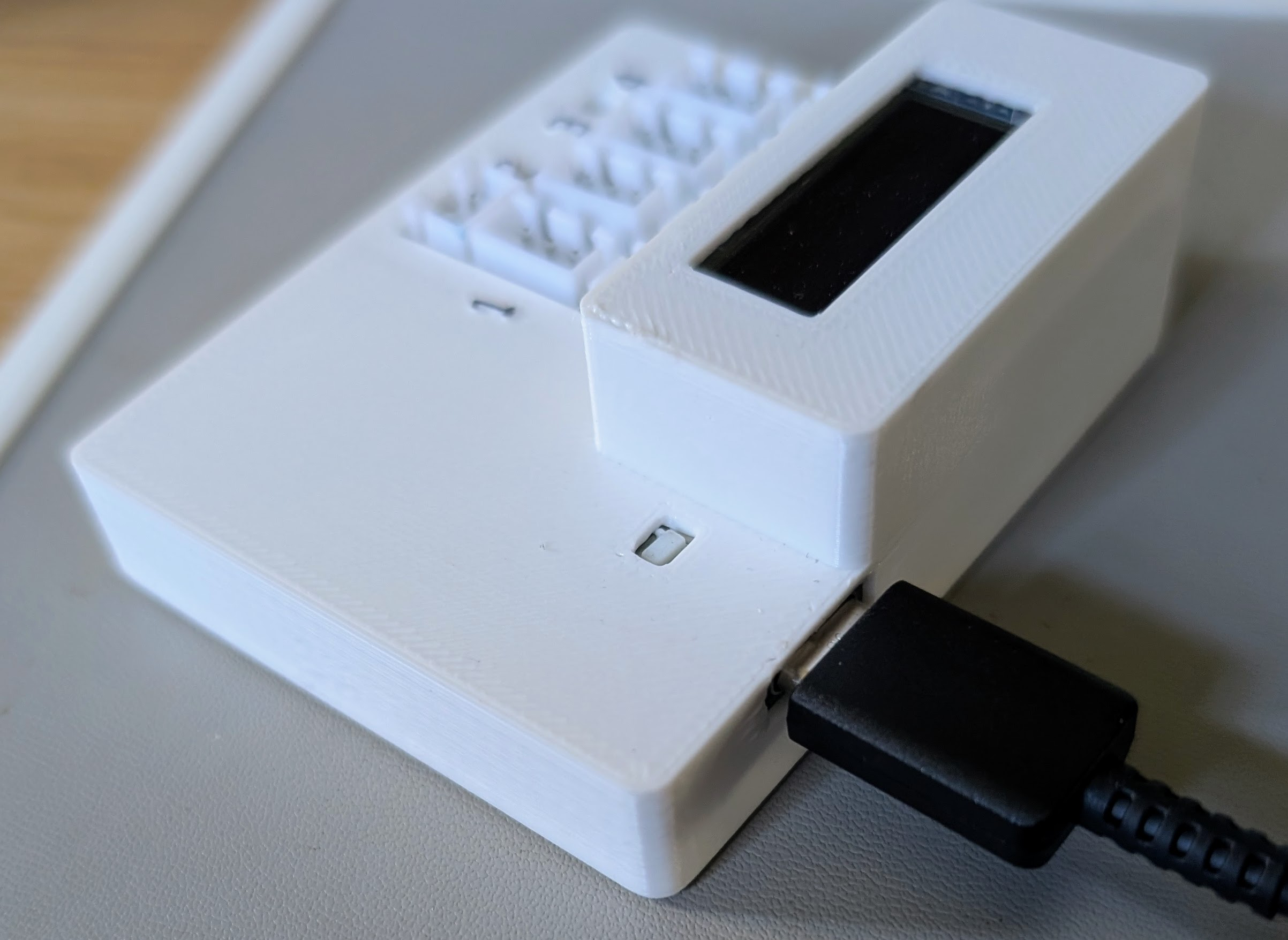
So far, I have updated the Garage133 and Plant133 boards to use native USB-C, since both run from standard 5V USB wall adapters. For my solar-powered Garden133 boards, for now I kept the daughterboard system: they run on batteries, already require opening their weatherproof housing for servicing, and this lets me use up my remaining stock of micro-USB receptacles.
Thermal Isolation and Sensor Accuracy (SHTC3)
On the latest Garage133 revision, along with upgrading to USB-C, I wanted to address temperature sensor accuracy. The Garage133 board, like many of my designs, includes an SHTC3 temperature and humidity sensor, and past revisions consistently read a few degrees higher than ambient. The layout of the previous version did not account for board self-heating.
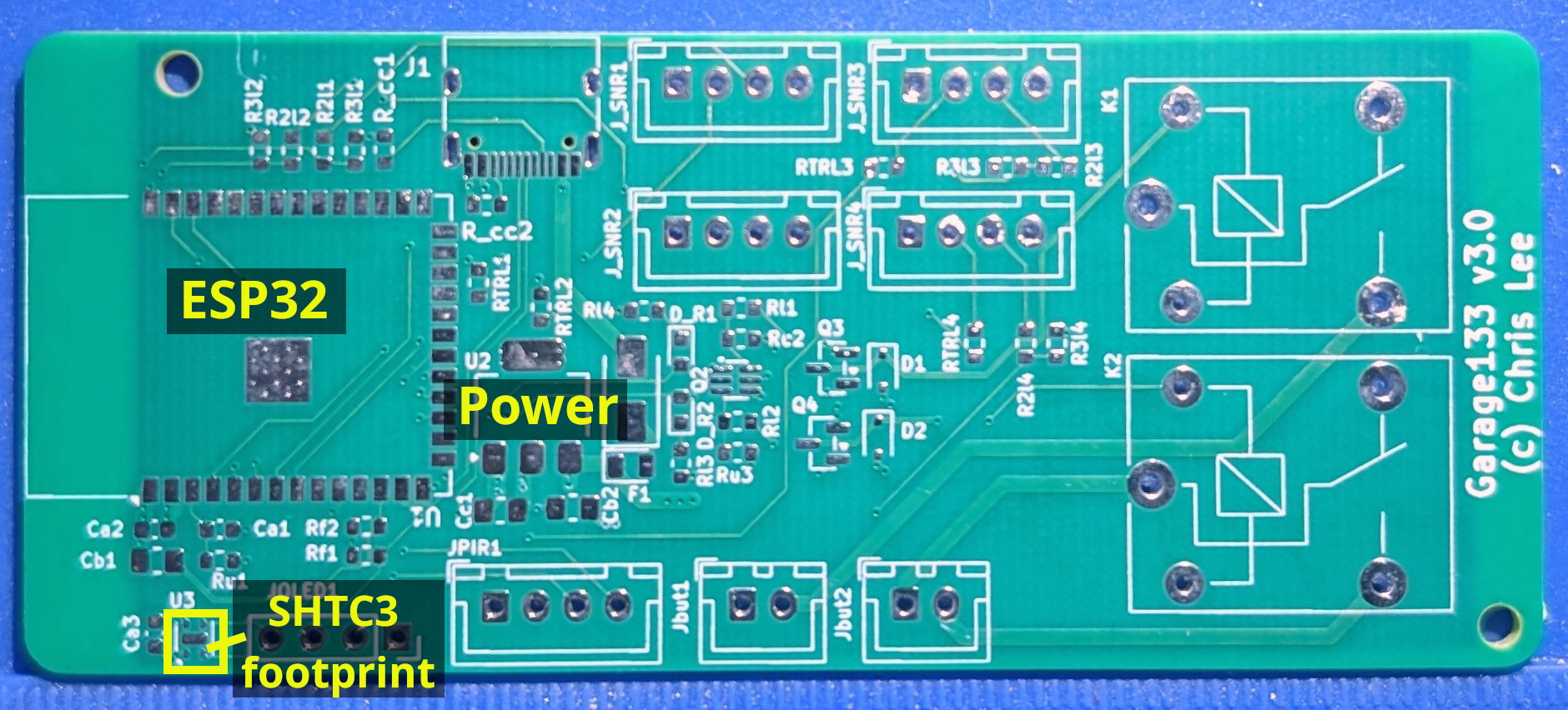
The image above shows the footprint for the SHTC3 sensor at “U3” near the bottom-left corner of the board. Reviewing this layout highlights several thermal mistakes:
- The sensor sits immediately adjacent to the ESP32 module and the 3.3V linear voltage regulator. The ESP32 draws intermittent 200–300 mA current spikes during Wi-Fi transmission, and the LDO drops 5V down to 3.3V, dissipating the voltage difference as heat. These two components represent the primary heat sources on the board.
- The continuous copper pours of the ground and 3.3V power planes run unbroken beneath the ESP32, the voltage regulator, and the SHTC3. Because copper is an efficient thermal conductor, the internal planes act as a heat sink that conducts thermal energy directly into the sensor package.
- There is no physical isolation or thermal relief separating the sensor from the main PCB body.
The design of the v3.1 board addresses these issues, as shown below. This is the PCB with surface-mount components, before the through-hole components are soldered to the board.
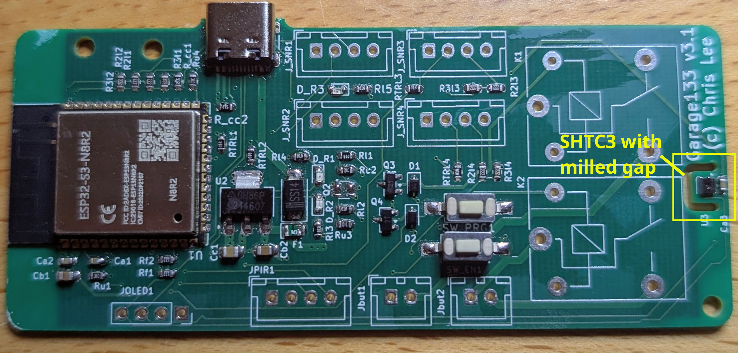
The sensor is relocated to the far edge of the board, as distant from the ESP32 and voltage regulator as board dimensions permit. The large blue relays can generate heat when energized, but in a garage door controller they only trigger for a brief pulse to actuate the door mechanism. Crucially, all copper pours terminate before reaching the sensor peninsula, and a milled slot removes the PCB substrate around three sides of the footprint. Because air is a much poorer thermal conductor than copper or FR4 fiberglass, this slot breaks the thermal conduction path. Only narrow signal traces bridge the gap to supply 3.3V power and I2C communication.
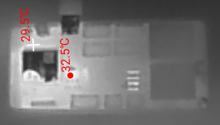
Below is a thermal image of the updated, powered Garage133 board. The voltage regulator and ESP32 are clearly the hottest parts of the board. The SHTC3 on the right is well isolated from the heat, sitting on a tab bounded by the milled slot.
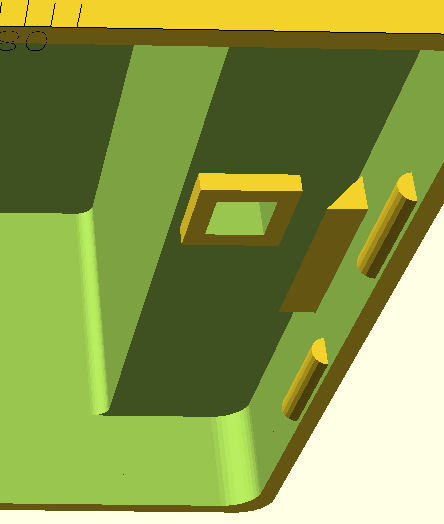
The enclosure design was also updated to help isolate the SHTC3.
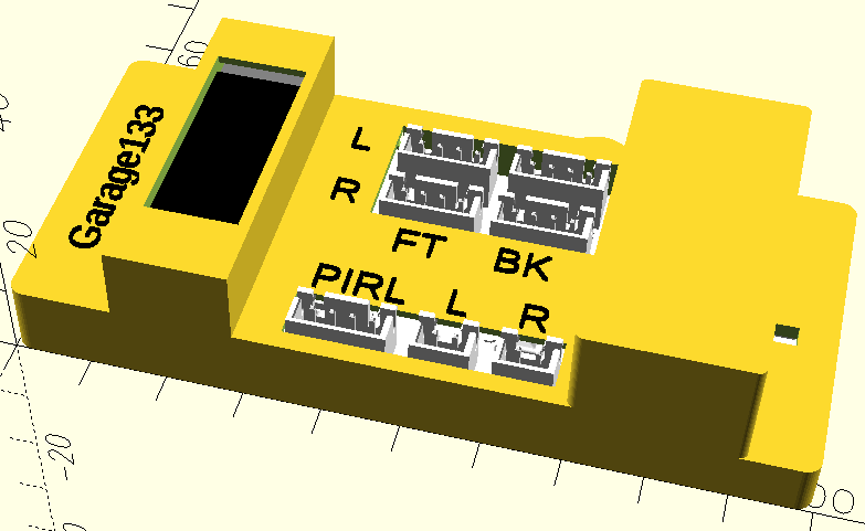
At the sensor end, the top of the case drops down close to the surface of the board. An air hole exposes the sensor to ambient air, and a small skirt reaches down to isolate the sensor from the warm air inside the rest of the enclosure.
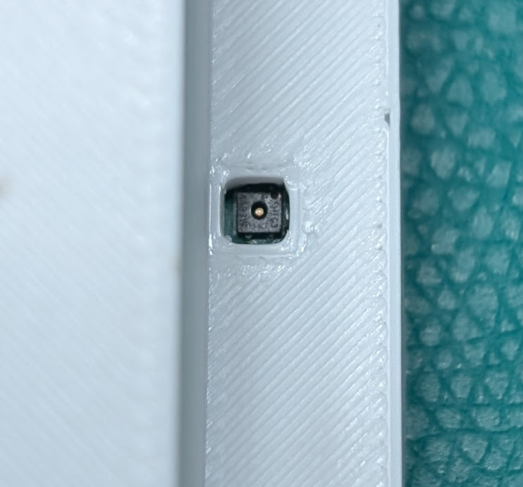
The photo below shows the sensor aligned directly beneath the exterior air hole.
Thermal isolation could be improved further by introducing a baffle in the case bottom to block airflow below the board.
Conclusion and Project Status
This revision brings together several iterative improvements across my home sensor hardware:
- Migrating to native USB-C on the ESP32-S3 for single-cable programming and debugging on Garage133 and Plant133.
- Implementing routed thermal air slots and severed copper pours to isolate the SHTC3 sensor from on-board heat sources.
In parallel with these board redesigns, I also streamlined my workshop assembly process in Faster SMD Pick-and-Place .
The latest PCB designs and firmware are available in the Plant133 and Garage133 GitHub repositories.
Have you migrated your own ESP32 boards to native USB-C, or used routed air slots to isolate ambient sensors? I would be interested to hear how you handle thermal isolation in compact 3D-printed enclosures. Let me know in the comments below!
References
-
An SHTC3 module is a temperature and humidity sensor that communicates with a microprocessor using I2C ( AliExpress ) ( Datasheet ). ↩︎
-
ESP8266 : a low-cost Wi-Fi microchip, with built-in TCP/IP networking software, and microcontroller capability, produced by Espressif Systems. ↩︎
-
The CH340C is a low-cost USB-to-UART bridge IC that converts USB signals into standard serial (TTL/UART) data with a built-in clock generator. (at LCSC ) ↩︎
-
ESP32 : a family of microcontrollers made by Espressif Systems, and the successor to the ESP8266 microcontroller. ↩︎