Garden133 Firmware: Power-Efficient C++ Code For ESP32, With Deep Sleep and LoRa
Posted on August 9, 2025 • 6 min read • 1,212 words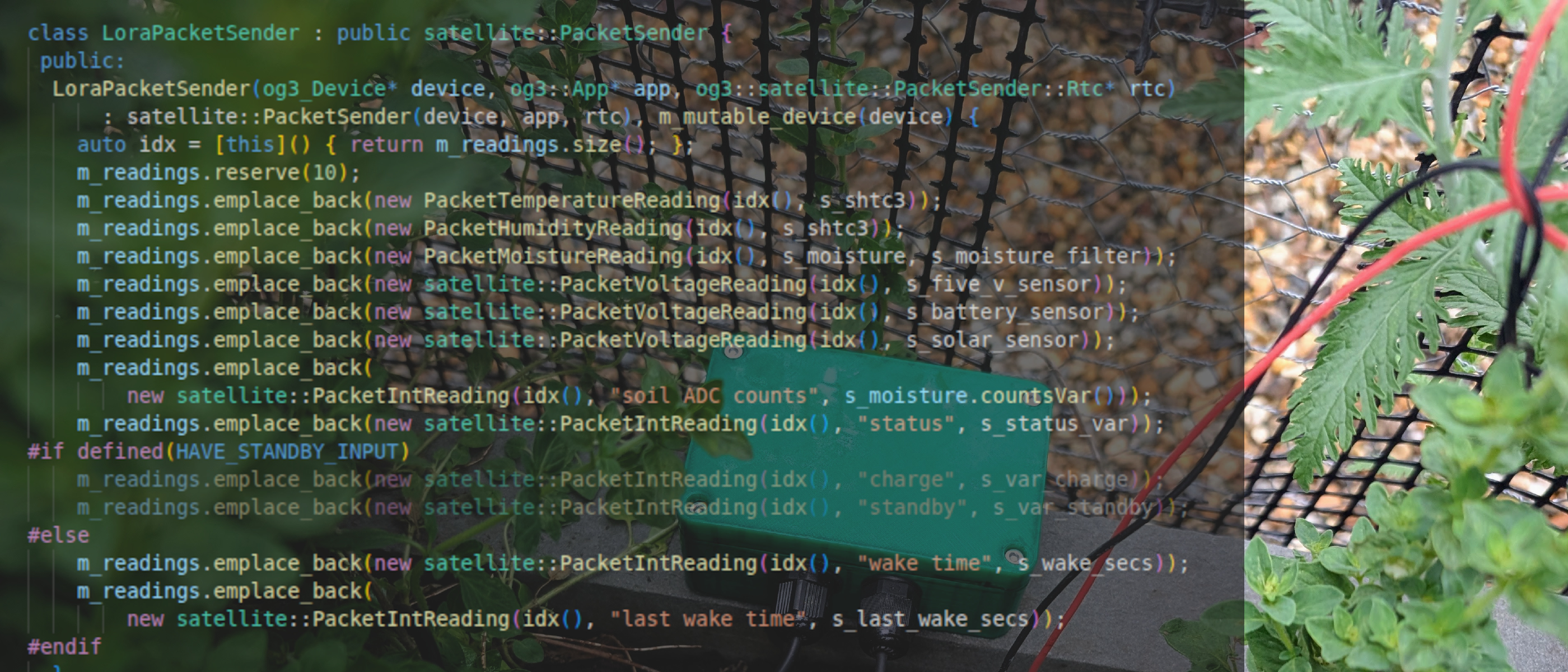
The Brains of the Device: Garden133 Firmware
The Garden133 system monitors garden soil moisture levels, to help with automated garden watering. If the hardware is the body of the system, firmware is the brain that makes it alive. This post covers how the code balances monitoring soil moisture while surviving on a limited solar-charged battery. The code implements a satellite communication architecture using LoRa1 radios.
The system relies on two distinct pieces of firmware: one for the satellite units
sitting in the dirt, and one for the base station acting as a gateway to the house.
Both are written in C++2 and use my og33 framework to structure the code
into modules, automate web configuration, and integrate with Home Assistant4.
Satellite Unit Firmware: Surviving on an Energy Budget
Integrating ESP32 Deep Sleep
The satellite units operate with a strict cycle: wake up, report soil conditions, and get back to sleep as quickly as possible to save power.
- They power on only long enough to sample sensors and fire off a LoRa packet.
- Then, they command the LoRa module to sleep.
- Finally, they set a timer for 5 minutes and drop the ESP32 into “deep sleep” mode.
When the ESP32 wakes from deep sleep, it’s essentially a fresh boot.
We can call the function esp_sleep_get_wakeup_cause() to see whether it is actually
booting or whether it has been awakened from deep sleep by a timer, an external signal, or
some other mechanism.
This article
from Random Nerd Tutorials provides a good explanation.
To keep track of things like the packet sequence number or the state of moisture filters
during deep sleep, we have to store data in a special section of memory marked with
RTC_DATA_ATTR.
This led to a particularly fun “learning opportunity” during development. I’m so used to initializing my variables that I reflexively added initializers to the RTC struct:
// This data should persist during deep sleep.
// DO NOT SET INITIALIZERS ON THESE VALUES!
RTC_DATA_ATTR struct {
  unsigned bootCount; // I initially wrote: unsigned bootCount = 0;
  byte mac[6];
  KernelFilter::State<kFilterSize> filter_state;
  // ...
} s_rtc;
It took me an embarrassing amount of time to realize that by adding = 0, I was telling
the bootloader to overwrite my saved data every time the board woke up.
Once I removed the initializers, the persistent memory finally started working.
Debug Mode: Making Garden133 Maintenance-Friendly
A device that sleeps for 299 out of every 300 seconds is hard to configure.
To solve this, I added a “Debug” toggle.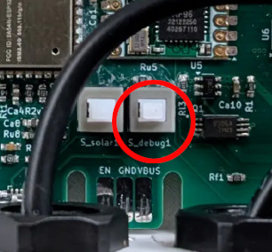
To reach the toggle, you do need to unscrew and open the sealed enclosure. However, when the toggle depressed, the firmware skips deep sleep and enables:
- WiFi & Web Interface: Allowing for configuration of WiFi, the moisture sensor, the LoRa radio, and MQTT5.
- Over-the-Air (OTA) Updates: So I can fix bugs without removing the PCB and attaching a serial cable.
Base Station Firmware: The LoRa-to-MQTT Gateway
While the satellites are optimized to run only briefly before sleeping, the base station is a permanent resident of the house with its own USB power supply, so it is always running. Its job is to listen for the satellites’ LoRa packets and translate them into a language Home Assistant understands. Garden133 Radio details the content and format of these packets.
Using the og3x-satellite library, the base station automatically implements the Home Assistant MQTT Discovery protocol on behalf of satellite units. This means that as soon as I deploy a new sensor, it automatically appears in my dashboard with all its entities pre-configured.
An example from the soil moisture sensor reading of the sensor for the satellite unit
monitoring our “Raised bed #1” is shown below.
It is sent to MQTT topic
homeassistant/sensor/lora133b/raised-bed-1_soil_moisture/config.
{
  "~": "og3/lora133b",
  "avty_t": "~/connection",
  "pl_avail": "online",
  "pl_not_avail": "offline",
  "device": {
    "name": "raised-bed-1",
    "ids": "raised-bed-1_5db6",
    "mf": "c133 org",
    "mdl": "LoRa133",
    "sw": "LoRa133 v0.5.0",
    "via_device": "8813BF012878_LoRa133",
  },
  "unit_of_meas": "%",
  "stat_t": "~/raised-bed-1_5db6",
  "val_tpl": "{{value_json.soil_moisture|float|round(1)}}",
  "dev_cla": "moisture",
  "name": "soil_moisture",
  "uniq_id": "raised-bed-1_5db6_soil_moisture",
  "state_class": "measurement"
}
With an entry like this for each sensor in the device, the device is automatically added to Home Assistant.
When a LoRa packet from this satellite unit with sensor reading values is received by the base
station, it is translated to a packet like this sent to topic
og3/lora133b/raised-bed-1_5db6:
{
  "dropped_packets": 87,
  "RSSI": -102,
  "temperature": 23.85,
  "humidity": 27.06,
  "soil_moisture": 92.09239,
  "fivev_voltage": 3.992871,
  "solar_voltage": 3.876855,
  "soil_ADC_counts": 1408,
  "status": 4,
  "charge": 1,
  "standby": 0,
  "battery_voltage": 4.100391
}
Here is the Home Assistant device view after this message was parsed.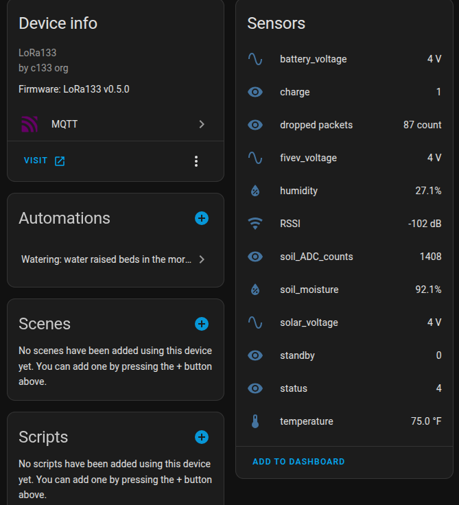
Modular C++ with the og3 Framework
I wrote the firmware for these devices using my og3 library.
Here, “og” stands for
original gangsta because
it is an old-school C++ library and application framework, not one of those trendy
YAML-based
frameworks like
ESPHome that the kids these days are using.
This is partly because I want the control that writing firmware directly in C++ provides, and
partly because I’m a programmer so my hobby projects involve real programming, dammit!
In og3, code is organized into
Modules.
Each module (WiFi, MQTT, Sensors) has a defined lifecycle:
link(), init(), start(), and update().
This allows me to build complex dependencies, like a web server that only starts once
WiFi is confirmed, without creating a spaghetti-style main loop.
graph LR
   B[Config] --> A[Flash]
   C[Wifi manager] --> B
   D[MQTT manager] --> C
   E[HA discovery] --> D
   F[Web server] --> C
   G[OTA manager] --> C
A simplified version of the satellite unit’s main loop demonstrates this modularity. It waits for the LoRa module to be ready, sends a single packet, and then uses a task scheduler to trigger the next sleep cycle.
void loop() {
  og3::s_app.loop(); // The og3 framework handles the module updates

  // If we aren't in debug mode, send our data once.
  if (!og3::s_is_debug_mode && og3::s_lora.is_ok()) {
    static bool s_sent = false;
    if (!s_sent) {
      og3::s_packet_sender.update();
      s_sent = true;
    }

    // After the radio has finished sending the data, just once,
    //  schedule the board to go into deep sleep.
    static bool s_sleep_started = false;
    if (!og3::s_packet_sender.is_sending() && !s_sleep_started) {
      og3::s_app.tasks().runIn(og3::kMsecInSec, og3::start_sleep);
      s_sleep_started = true;
    }
  }
}
Conclusion
The firmware for Garden133 is based on the same og3 framework that holds my other projects
together.
However, it adds power management, LoRa radio, and a satellite communication architecture.
The complete firmware is available at GitHub under the MIT license.
- Satellite unit: Garden133 GitHub repository.
- Base station: LoRa133 GitHub repository.
These both depend on the following libraries:
- Application framework:
og3. - Satellite communication architecture:
og3x-satellite. - LoRa module support:
og3x-lora.
References
LoRa (the name stands for “long range”) is a physical proprietary radio communication technique ( Wikipedia, Semtech). It is specialized for long range, low bandwidth, low power radio communication for Internet of Things (IoT) applications. ↩︎
C++ is a high-level, general-purpose programming language created by Danish computer scientist Bjarne Stroustrup. ( Wikipedia). ↩︎
og3is my C++ utility library for ESP microprocessors, published on GitHub. ↩︎Home Assistant is a popular Open Source home automation platform. It is the hub for my own smart home, and it is fun to work with. ↩︎
The MQTT protocol ( Wikipedia) is useful for IOT (Internet of Things) applications. ↩︎