Garden133 Hardware: Solar-Powered, ESP32-Based Soil Moisture Sensor System Design
Posted on June 21, 2025 • 18 min read • 3,671 words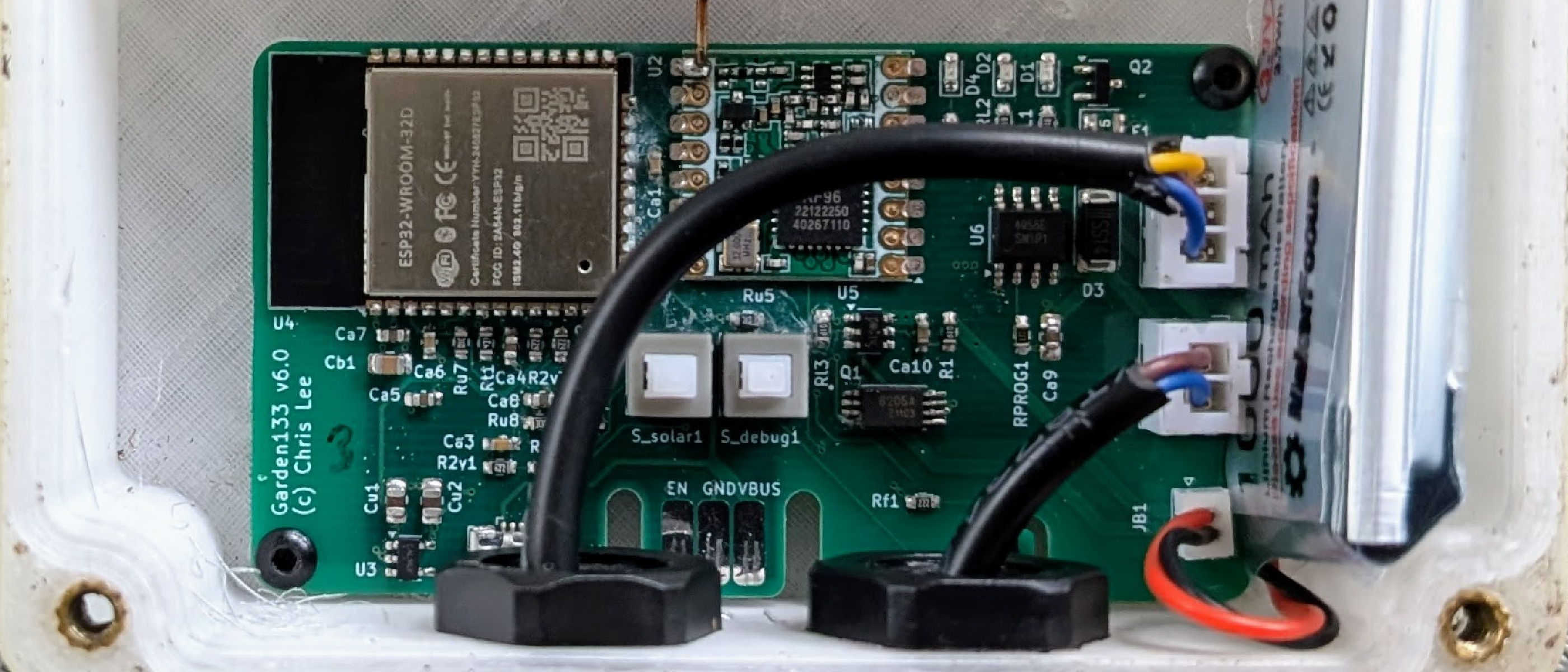
Following up on the Garden133 overview, this post details the physical implementation of the system.
Getting soil moisture data from a garden to a home automation system requires hardware that can survive outdoors without a power cord. This requires battery power, solar charging, robust radio communication, and a waterproof enclosure. I’ve documented the electronics, sensors, and the 3D-printed components here. The KiCAD1 and OpenSCAD2 designs are Open Source and available at the Garden133 and LoRa133 GitHub repositories.
This post is sponsored by PCBWay, who generously manufactured the PCBs for the garden sensor boards to help with this blog.
Hardware System Requirements
The goal was to design a sensor unit that could live in the yard indefinitely. This led to several specific requirements:
- Self-powering: Use solar power to recharge a battery since there are no outlets in the garden.
- Range: Use a radio capable of reaching the house from all corners of the yard.
- Durability: Survive the rain and temperature swings of a New England growing season.
- Maintainability: Include a “debug mode” for configuration and firmware updates without needing to fully disassemble the unit.
I also wanted to keep the per-unit hardware cost relatively low.
Hardware System Architecture: Solar, Sensors, and LoRa
The physical components of the Garden133 system are the sensor units which live in the garden, and the base station in the house.
To allow them to operate indefinitely outdoors, the sensor units have a battery and a solar panel. They run on solar power when available, and battery power otherwise. When the solar panel is powering the device, it is also recharging the battery. The sensor units are designed to use as little power as possible, so they keep working even during long periods with very little sun.
Since the sensor units live outdoors in the yard and garden, they need a weatherproof enclosure to protect them from the rain.
For communication, I chose a satellite architecture where the sensor units send information to the home automation system via LoRa3 radio links to a base station. The base station receives data packets from the sensor units via LoRa, and translates these into MQTT4 messages that are sent to the local server via WiFi.
If you open the sensor unit and press a toggle button, this puts the sensor board into “debug mode.” In this mode, the board connects to the home WiFi network (so I take the board back into the house when doing this), and it implements a web interface where the unit can be configured or its firmware updated.
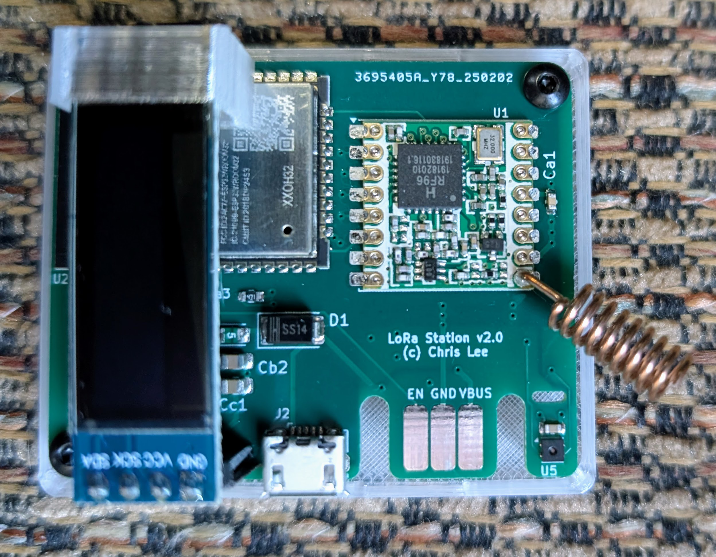
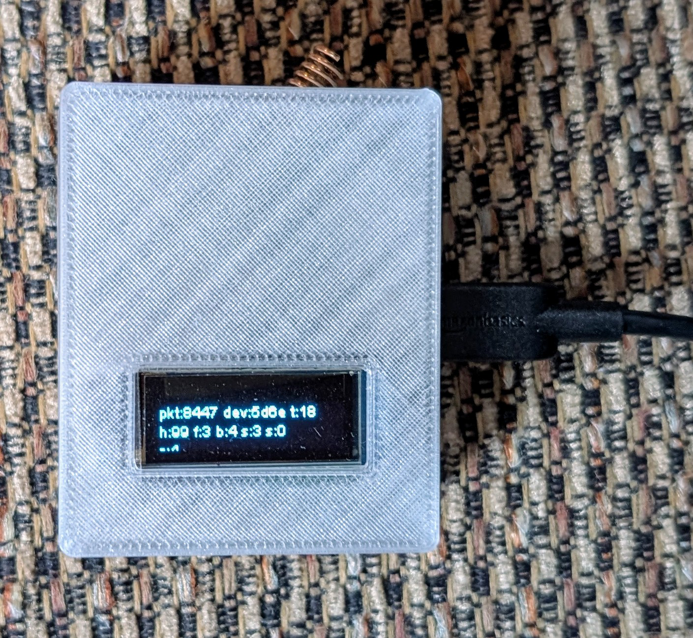
LoRa to WiFi Base Station Hardware
The base station is the simplest component of the system. It is a basic PCBA with an ESP325 microprocessor, a RFM95W LoRa radio module, and a standard 3.3V regulator. It has a SHTC3 temperature/humidity sensor and a small OLED display. The display shows basic information such as the name IP address of the board, the current sensed temperature and humidity, and information about the latest packet of data received from a sensor unit. It runs open source firmware written in C++ using my og36 software framework.
For maximum range, perhaps unnecessarily since the sensor units are in the yard not too far away, the base station is mounted high in the attic of the house. Thus the base station also serves the purpose of monitoring conditions in the attic, which can get very hot in the summer. It exceeded 53°C (128°F in “freedom units”) while I was writing this post.
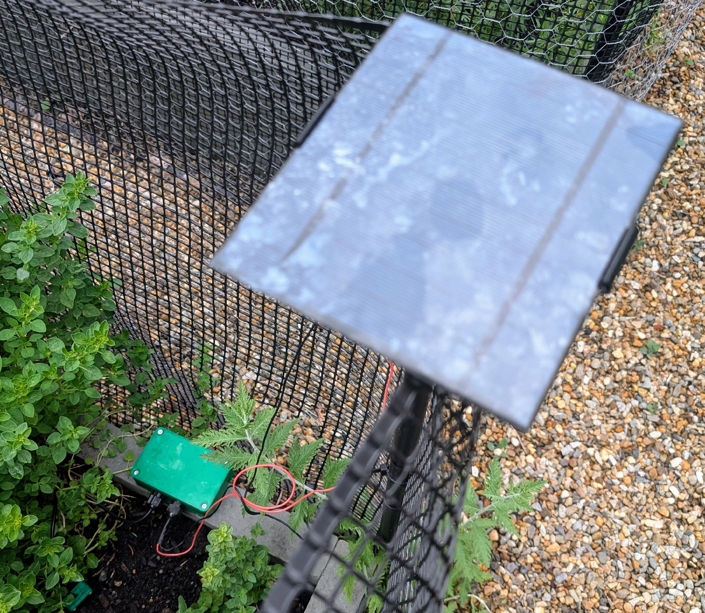
Solar-Powered Garden Sensor Unit Design
The far more interesting piece of hardware is the garden base station. Its job is to read a moisture sensor to monitor soil conditions, and to send this information by radio to the base station. The garden base station seems alive in some ways. It operates on its own, powered by sunlight, like the plants alongside it in the garden.
Selecting and Protecting the Capacitive Soil Moisture Sensor
The entire point of the project is to monitor soil moisture, so the moisture sensor is the heart of the device. I’m using the same capacitative sensor as in the Plant133 project. Andreas Spiess compares this and other sensors in one of his well made YouTube videos. A similar project, described in this blog post, has a good write-up on how to calibrate this sensor.
At first I didn’t notice that there are two versions of the capacitative sensor. The way my board was originally designed, the moisture sensor was powered by a voltage that might come from either the battery or the solar panel. I thought the sensor had an internal 3.3V voltage regulator, so that the power need only be between 3.3-5V. However, I noticed that the moisture reading sometimes changed when I knew it shouldn’t. It became apparent the moisture reading was varying with the voltage supplied to it. It turns out that sensors labeled “v1.2” use a resistor rather than a voltage regulator. I switched to sensors labeled “v2.0” which actually have their own regulator, and found their readings much more reliable. These should also be more energy-efficient. For extra consistency, I now power the sensor using the board’s 3.3V regulated power.
After watching the performance further, I realized that the moisture level readings could still change when they shouldn’t. I found that readings are not reliable when the supply of power to the board’s 3.3V regulator drops below 3.3V. This is despite the fact that the ESP32 microprocessor and radio module continue to function. This condition occurs when the board is running on solar power, but in low light. E.g., when it is very cloudy, or at dawn/dusk. I decided to deal with this by simply ignoring these moisture sensor readings. The moisture level of soil in the garden doesn’t change very quickly. If we have to throw away some readings, that isn’t exactly the end of the world.
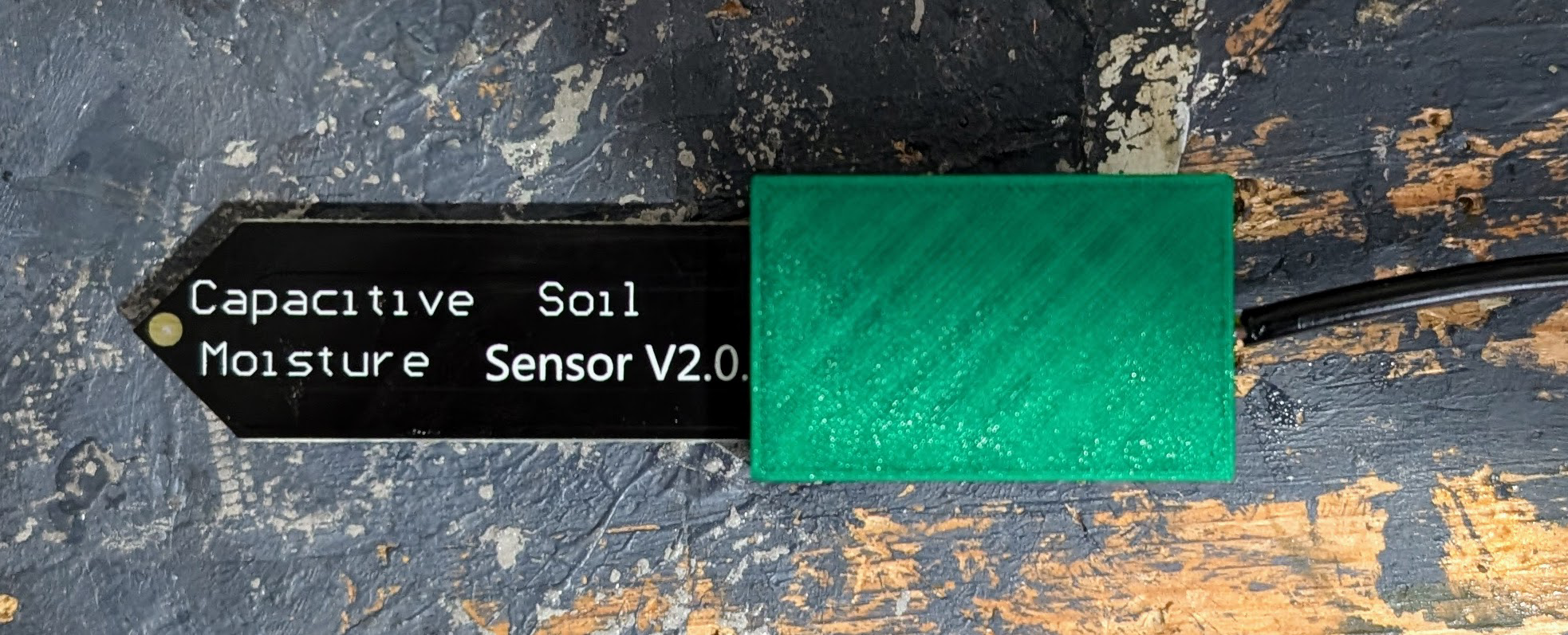
The sensor has its electronics exposed, which makes it unsuitable for outdoor use.
I first tried protecting the sensor by covering the electronics with a potting
compound7.
This worked, but it was kind of a pain, it was expensive, and the warning label on the
compound I tried was a bit terrifying.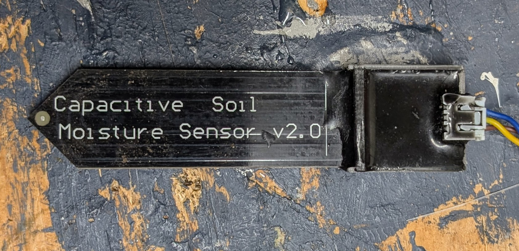
I eventually saw that other people simply make a cap for the sensor and fill it with silicone to protect it from moisture. My design for the moisture sensor cap is in the GitHub repository for this project and also on Printables. It allows the JST connector to be inside the protected space, and has an otherwise fairly tight fit to limit the amount of silicone needed.
I’ve since also learned that it is a good idea to seal the edges of the moisture sensor PCB with epoxy or similar protectant (see Improving Reliability for ESP32 Plant Watering Systems: Lessons from Plant133).
Designing a Solar/Battery Power System with TP4056
The power system, integrating battery and solar power, was the most challenging part of the design.
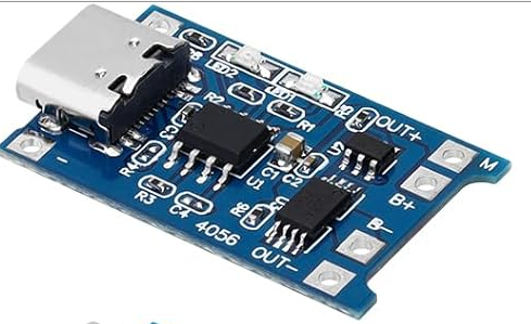
The battery charger module: TP4056
The garden sensor board is powered by solar power and battery, and the solar panel charges the battery. It uses a 3.7V Lithium rechargeable battery. Battery charging is managed by a TP4056 module. It is not a trivial matter to safely charge a Lithium battery. The TP4056 monitors the voltage and manages the current that flows into the battery. If the TP4056 thinks that all its output is going to charge the battery, but instead some of that output is also powering the rest of the board, then the module will not detect when the battery is near full. This could mean it doesn’t stop charging the battery even when it is full. This is not safe – we definitely do not want any chance of a Lithium battery fire.
Safe battery charging in a solar-powered device
A common way to avoid this problem employs a P-channel MOSFET8. This ensures that when the battery is charging, the battery is disconnected from the rest of the board. In this case, the same solar power that is used to charge the battery is also used to power the board. When there is not enough solar power to charge the battery, the board is switched back to battery power. This technique is discussed in the Microchip appnotes for the AN1149 module, and in these blog notes. Also see this Instructable writeup.
The section of the circuit used to power the Garden133 board (minus the battery protection
component) is shown below.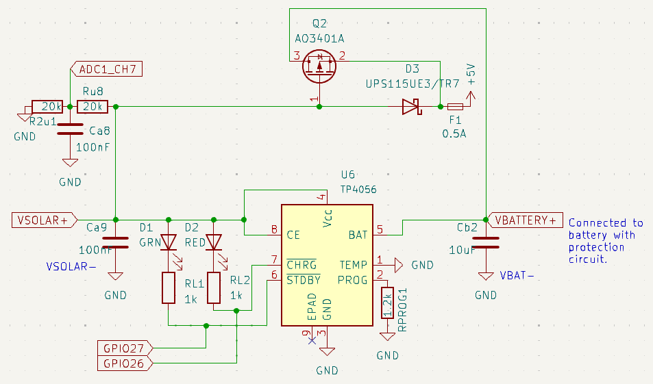
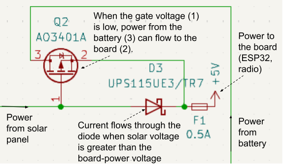
When the solar panel is producing a significant voltage, the TP4056 will be charging the battery. In this case the solar voltage to the gate of the P-channel MOSFET “Q2” causes the transistor to block current from the battery. Diode “D3” allows current from the solar panel to flow to the board instead.
Switching from battery to solar power
The switchover from battery power to solar power can be seen in the plot below.
To monitor the performance of the system, the ESP32 uses ADC9 inputs to monitor the voltages
of the battery, the solar panel, and the input to the 3.3V LDO regulator.
These voltage levels are sent to Home Assistant along with soil moisture levels, and these
values in turn go to
InfluxDB where I can generate graphical views with
Grafana.
I grabbed this plot from one of these views.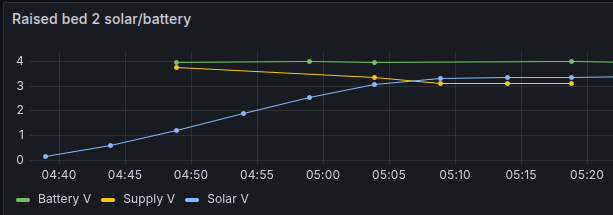
The yellow line “Supply V” is the power to the 3.3V regulator (this is the “+5V” in the circuit diagram). At the start of the plot, before 5am, the board is powered by the battery. Supply V is slightly below the battery voltage. The difference is due to the resistance across the P-channel MOSFET. The AO3401A was chosen for this role because it has a very low resistance (50-85mΩ) from drain to source when “on”. This minimizes power loss when the board is battery-powered, and is why the yellow line is very close to the green line at the left of the plot.
When the solar panel voltage rises past 3V, the transistor stops the flow of current from the battery. Current instead flows to the board from the solar panel through the Schottky diode. The voltage drop from the panel voltage to the “Supply V” voltage is the forward voltage drop of the diode. I chose a UPS115UE3/TR7 Schottky diode because it has a very small (220 mV) forward voltage. This allows the systems to perform better in low light: as mentioned before, the board does not trust moisture readings when “Supply V” is less than 3.3V.
This plot is from an earlier board with a different diode, so the drop from the solar voltage (blue) to supply voltage (yellow) at the right of the plot is greater than in the latest design.
Power system performance
In addition to the components listed above, most other components of the system are also chosen to lose as little power as possible. The 3.3V voltage regular is a NCP114ASN330T1G. It is designed for battery-powered applications, and has an operating input voltage range of 1.7V to 5.5V.
The ESP32 wakes from deep sleep, reads its sensors, sends the values to the base station using the LoRa radio, tells the LoRa radio module to go into sleep mode, sets an alarm to wake in about 5 minutes, and goes back into deep sleep mode. Based on the recommendation in Reducing RFM95 power consumption, I added pull-up resistors to the FS, MISO, and MOSI SPI connections to the radio module. Apparently if these pins float, this can cause the module to start consuming much more power than it should when in sleep mode.
Even when having the board wake every minute instead of every 5 minutes, and without putting the radio module into deep sleep, the battery alone (no solar panel connected) can run the Garden133 board system for more than a week. This is also without the board being connected to a moisture sensor. I’ll update this post with more representative results when they are available.
If I spent more time and taught myself a little more, I could probably determine the overall power draw of the system, determine how much power the different components are using when running and sleeping, and continue to optimize performance from there. But this is a hobby and I’m just a software guy. The solar panel easily recharges the battery in a few minutes, so in practice the system as it is works fine.
Solar panels
At first I used 5V, 500mAh, 2.5W Solar panels from Amazon. Later I tried a 3W 5V panel from AliExpress which was recently $3 and now is a little more than $5, possibly due to US tariffs.
Brown-outs
There is a problem with the power system. I found that if I sent more than two LoRa packets in quick succession after the board wakes, the board can brown-out before it sleeps again, and it can get lost in a boot-then-brown-out cycle. Instead of adding more capacitance or tracking down the problem, I took the lazy software engineer solution of making sure the radio protocol worked by sending only a single packet at a time after the initial system startup.
Radio modules
The Garden133 devices talk to the base station using LoRa radio modules. LoRa modules can be fairly inexpensive, and the protocol is designed for low-power, low-bandwidth communication with maximum range. It uses HopeRF RFM95W modules, which talk to the ESP32 via SPI10. The details of the radio connection link and the satellite sensor protocol I designed are the subject of a separate post.
Basic board and microprocessor
The base station and satellite units are designed around the ESP325 microprocessor. I chose it because I’m familiar with it, it has an ADC for reading the moisture sensor, built-in WiFi, a low power deep sleep mode, and there are libraries for integrating it with the LoRa module. The WiFi capability is used by the base station to talk to the MQTT server. The sensor units, when in debug mode, enable WiFi for configuration and maintenance. When “in the field” (or yard), in normal operation, these units save power by not enabling their WiFi radio.
I ordered the PCBs and a stencil from PCBWay, who sponsored this blog. I went to their web site, selected “PCB Prototype”, selected “Upload Gerber files,” and uploaded a zip-file containing the Gerber files generated by KiCAD from my board design. I filled out the web form, selected “HASL lead free” surface finish, and the smallest size stencil available. The 4-layer boards and stencil were finished and shipped only 4 days later. I received them a few days after that. I used the stencil to apply solder paste, and assembled the boards. They all worked perfectly.
This is the one of the boards as received, before assembly.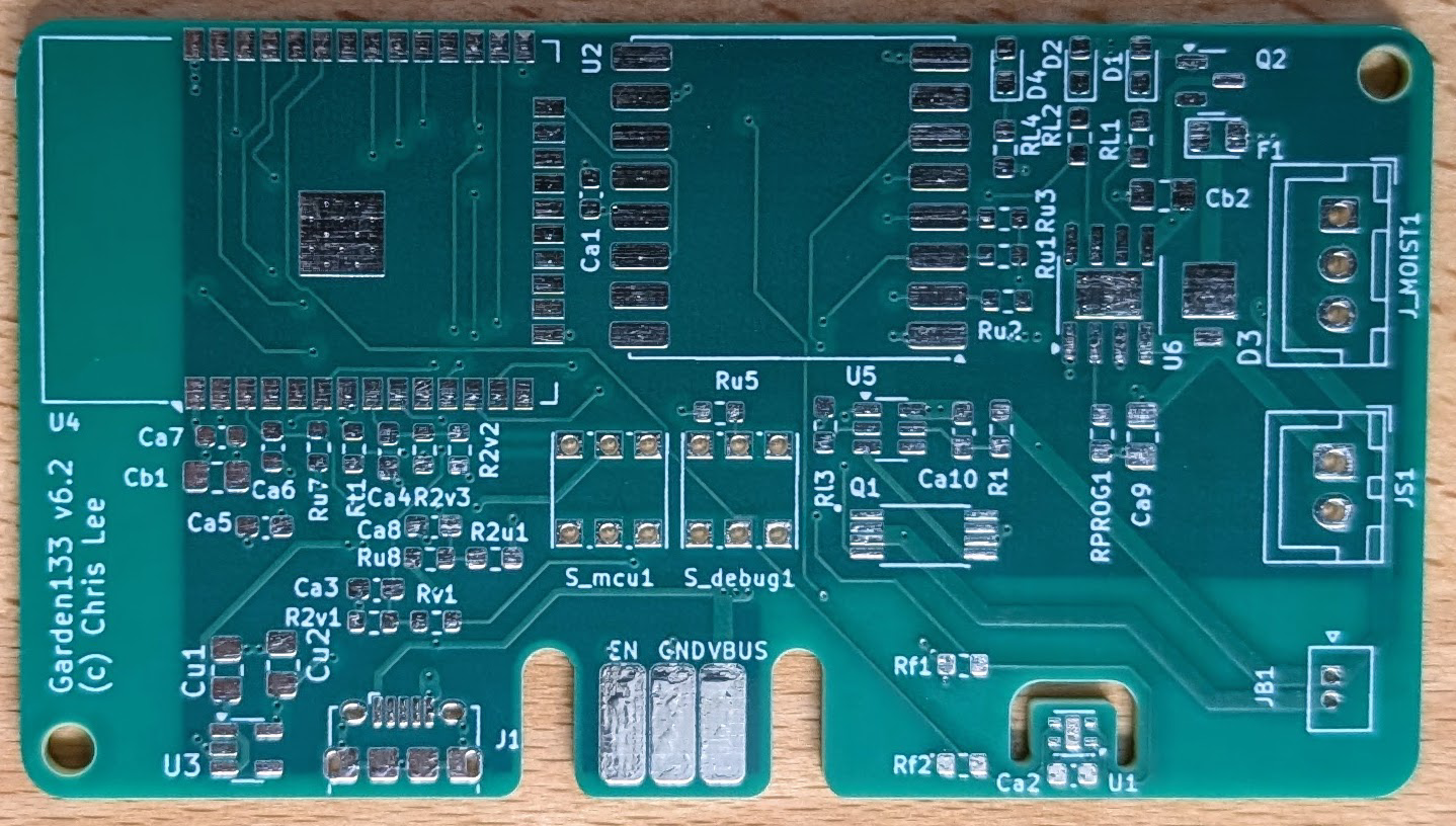
Here it is after assembly.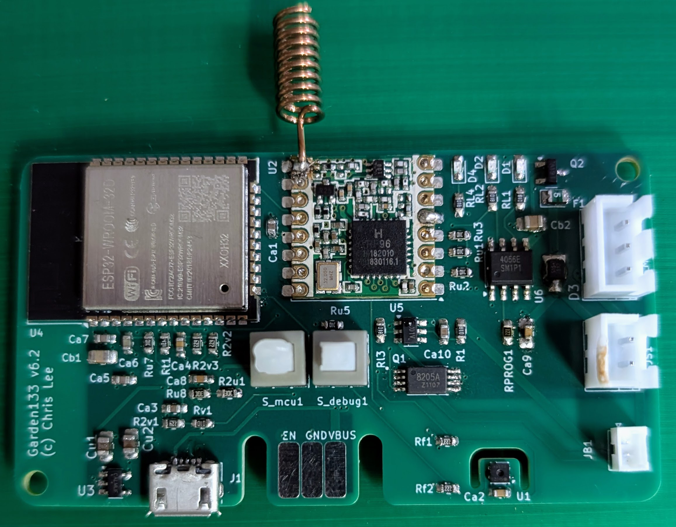
If you are interested this process, I wrote about it in DIY SMD PCB Assembly: Tools and Organization for Hobbyists and Improved PCB Stencil Alignment with 3D Printed Fixtures.
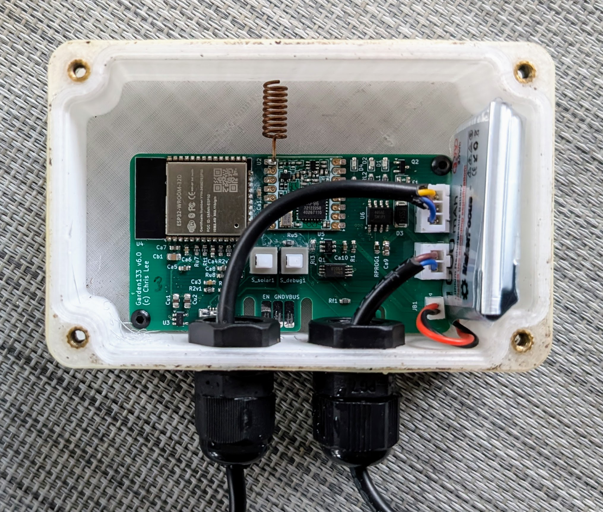
The toggle switches in the middle of the board control power to the 3.3V regulator (to turn on/off the ESP32, radio module, and moisture sensor), and enable/disable debug mode.
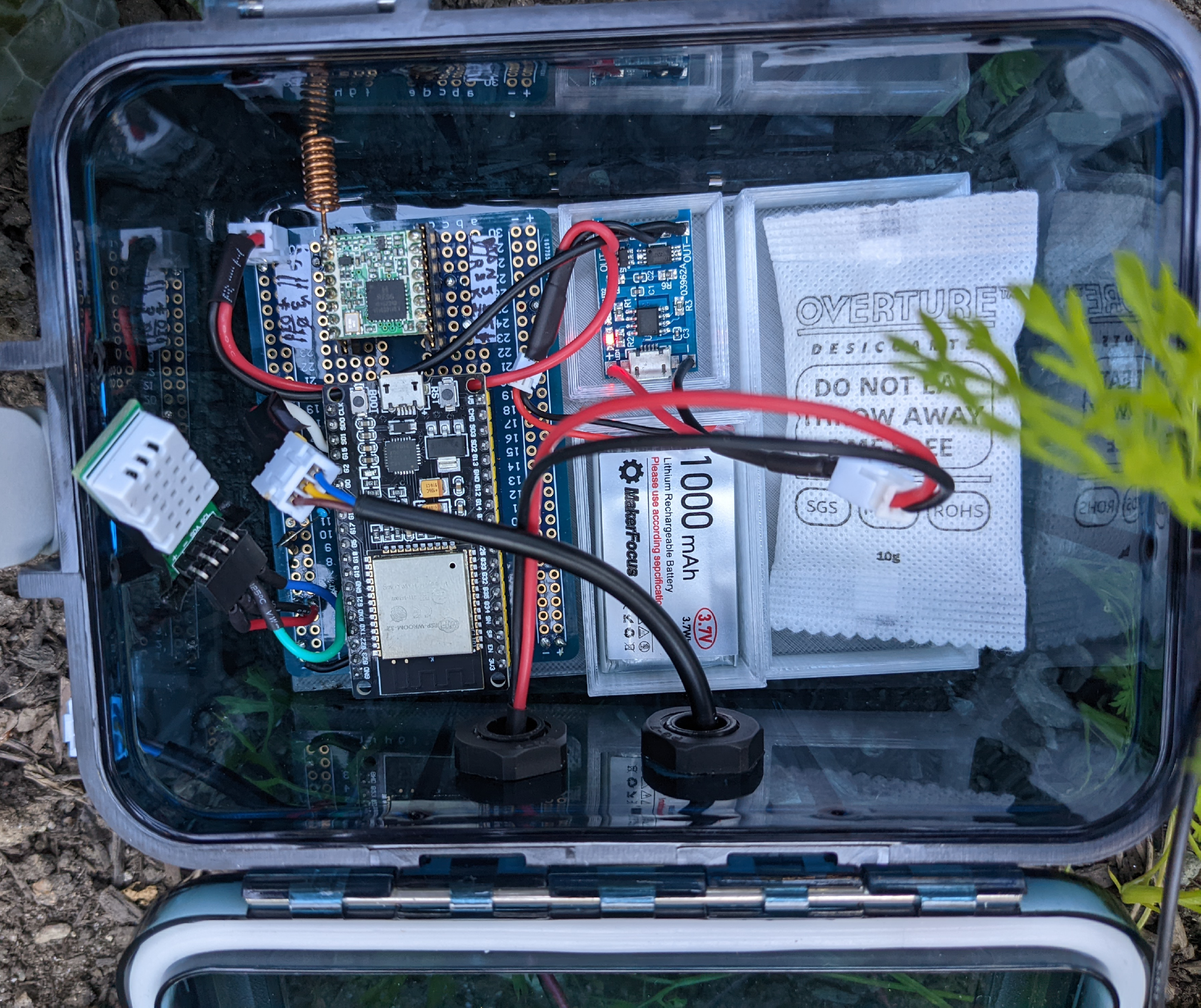
3D Printed Waterproof Enclosure Design
An early prototype of the sensor unit used a watertight box from
Amazon, which is designed for activities like kayaking.
I needed to drill holes in the side for the wires for the moisture sensor and solar panel.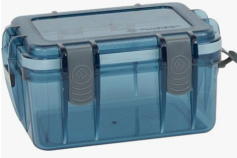
Later, I switched to 3D-printing a design based on the the open source customizable parametric enclosure system by pb-tec at printables.com. This is an incredibly useful parameterized OpenSCAD2 system for generating custom enclosures.
- I choose a size for the enclosure based on the size of the PCB, with extra space for the LoRa antenna and sufficient height for cable gland connections on the side of the box.
- I added holes on the side for two cable glands. One each for the wires to the solar panel and moisture sensor.
- I added screw-mounts for the board.
- I had 2mm Nitrile sealing cord ( AliExpress) from another project, so I selected a sealing-groove size to match that.
- I selected holes for threaded screw inserts and M3 screws to secure the lid.

The battery tucks-in nicely between the board and side of the enclosure. I printed in PETG, and used an Epoxy coating ( Amazon) to coat the outside of the enclosure to help waterproof it. I also coated the Nitrile sealing strip with silicone when I installed it to try to improve the seal.
Information about 3D-printing waterproof enclosures can be found at Watertight 3D printing part 2: Airtight closable models (Updated 2024).
Purchased components
I want the project to be low-cost. These are sources and the approximate prices for the important components of the project. Not all items are still available exactly as I bought them, but they can be easily found with some searching.
| Item | Source | Approximate cost |
|---|---|---|
| ESP-32S WROOM microprocessor | AliExpress | $1.60 |
| RFM95W 915MHz | AliExpress | $4 |
| Battery | Amazon | $4 |
| Solar panel | AliExpress | $5 |
| Cable glands | Amazon | 2x$0.40 |
| SHTC3 | AliExpress | $1 |
| 0.91" OLED | AliExpress | $1.50 |
| UPS115UE3/TR7 Diode | DigiKey | $0.69 |
| NCP114ASN330T1G 3.3V regulator | DigiKey | $0.18 |
| FS8205A (Dual N-Channel MOSFET) | AliExpress | $0.04 |
| AO3401A (P-Channel MOSFET) | AliExpress | $0.02 |
| DW01A battery protection IC | AliExpress | $0.10 |
| TP4056E battery charger | AliExpress | $0.10 |
Evolution of the Garden133 Sensor Prototype
The current design is the result of several prototypes and experiments.
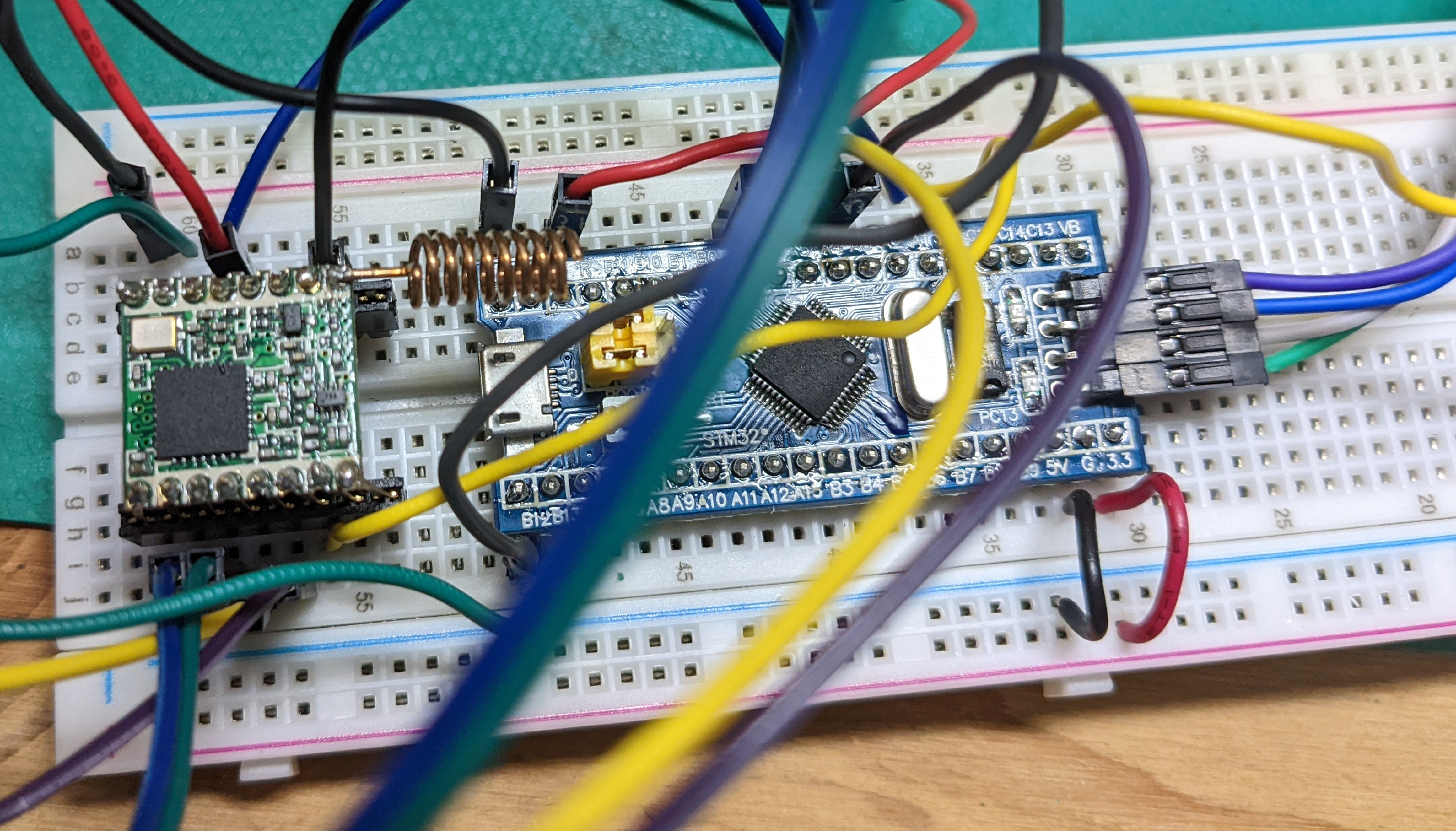
Blue Pill (STM32 clone)
I initially tried using a Blue Pill development board to experiment with a different microprocessor. Since the project used LoRa for communication, I didn’t strictly need built-in WiFi. I cobbled together a breadboard prototype with an adapter-header for the RFM95W module. However, I ran into issues with the software and floating-point arithmetic and eventually abandoned this path.
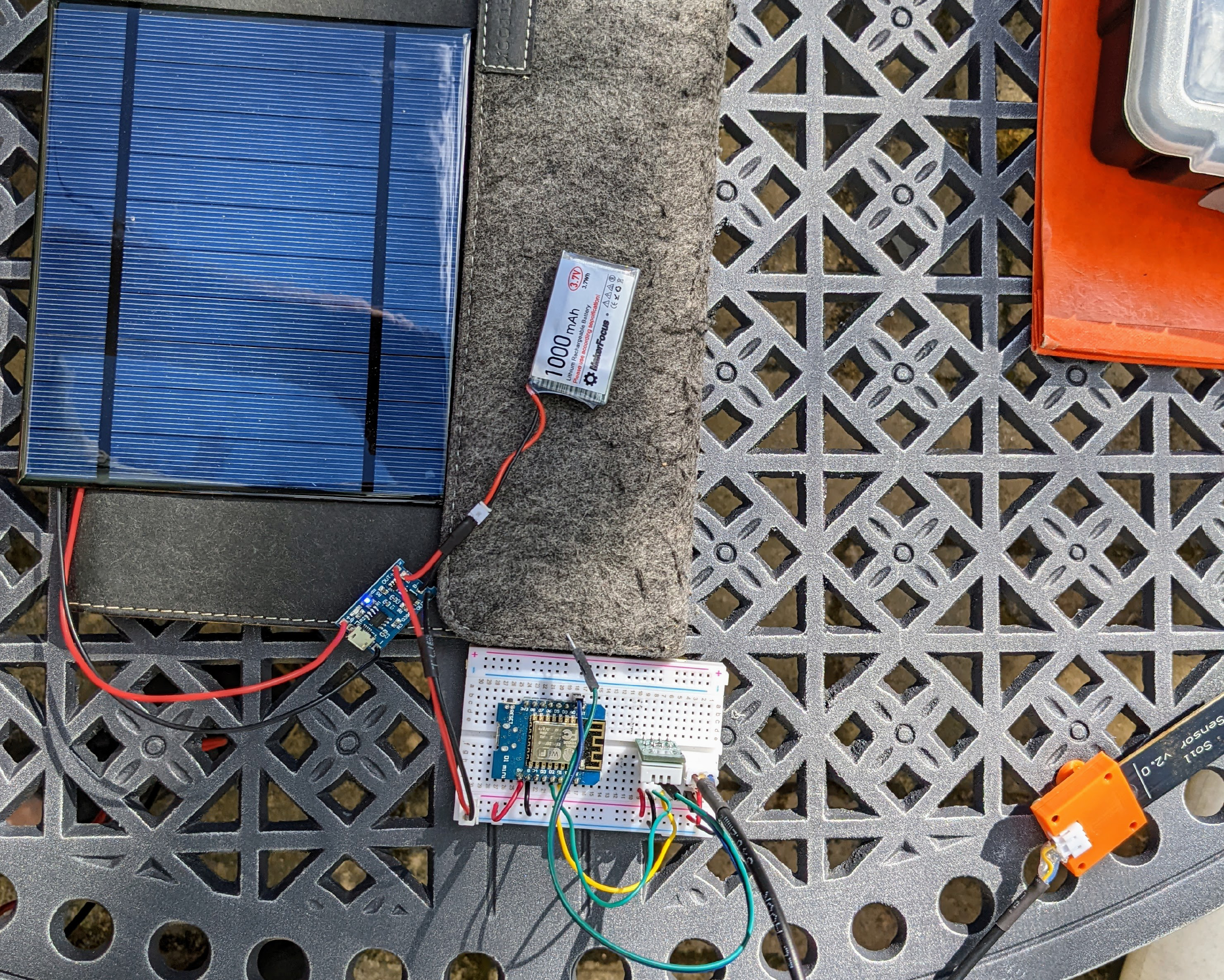
ESP8266
Next I tried the ESP8266, which I was using for a number of other projects at the time. While it worked and demonstrated how a battery and solar powered device could succeed, its power consumption was too high for a small solar-powered device. The low-power capabilities of the ESP32 proved to be a better fit for this application. Also, I had been migrating my projects in general to the ESP32. This more capable microprocessor would serve better as hardware and software needs scaled.
Modular ESP32 Devboard
I also tried a modular approach using an ESP32 developer board and a separate lithium battery charging board.
This functioned, but the ESP32 devboard drained the battery too quickly even in deep sleep. I aslo wanted to ensure the battery charging system implemented the important safety feature discussed earlier in this post.
Custom PCB
These prototypes eventually convinced me that I needed to design a custom PCB. This allowed me to control the design and selection of every component, ensuring better power management and more efficient solar charging. After a number of iterations, several of which didn’t work at all, the eventual result is the current v6.2 board which works quite well.
Conclusion
I managed to design a system which is working pretty well so far. It could still be improved to provide reliable readings in low-light conditions. If you are interested, please see my follow-up posts about the radio communication and software aspects of the system.
References
OpenSCAD is an open source program implementing a programming language for building 3D models. It is a way to build models using solid modeling primitives. ↩︎ ↩︎
LoRa (the name stands for “long range”) is a physical proprietary radio communication technique ( Wikipedia, Semtech). It is specialized for long range, low bandwidth, low power radio communication for Internet of Things (IoT) applications. ↩︎
The MQTT protocol ( Wikipedia) is useful for IOT (Internet of Things) applications. ↩︎
ESP32: a family of microcontrollers made by Espressif Systems. A successor to the ESP8266 microcontroller. ↩︎ ↩︎
og3is my C++ utility library for ESP microprocessors, published on GitHub. ↩︎Potting Compound: a substance used to fill an electronic assembly to keep out water, corrosive agents, and protect it in other ways ( Wikipedia). ↩︎
MOSFET. The metal–oxide–semiconductor field-effect transistor (MOSFET) has the ability tochange conductivity with the amount of applied voltage, and can be used for amplifying or switching electronic signals. Wikipedia. ↩︎
ADC. An analog-to-digital converter (ADC, A/D, or A-to-D) is a system that converts an analog signal, such as a sound picked up by a microphone or light entering a digital camera, into a digital signal ( Wikipedia). ↩︎
Serial Peripheral Interface (SPI) is a de facto standard, with many variants, for synchronous serial communication, used primarily in embedded systems for short-distance wired communication between integrated circuits. ( Wikipedia). ↩︎