Garden133 Power System Redesign: Sensor Power Control and Ideal Diodes
Posted on November 15, 2026 • Last modified on November 15, 2026 • 20 min read • 4,133 words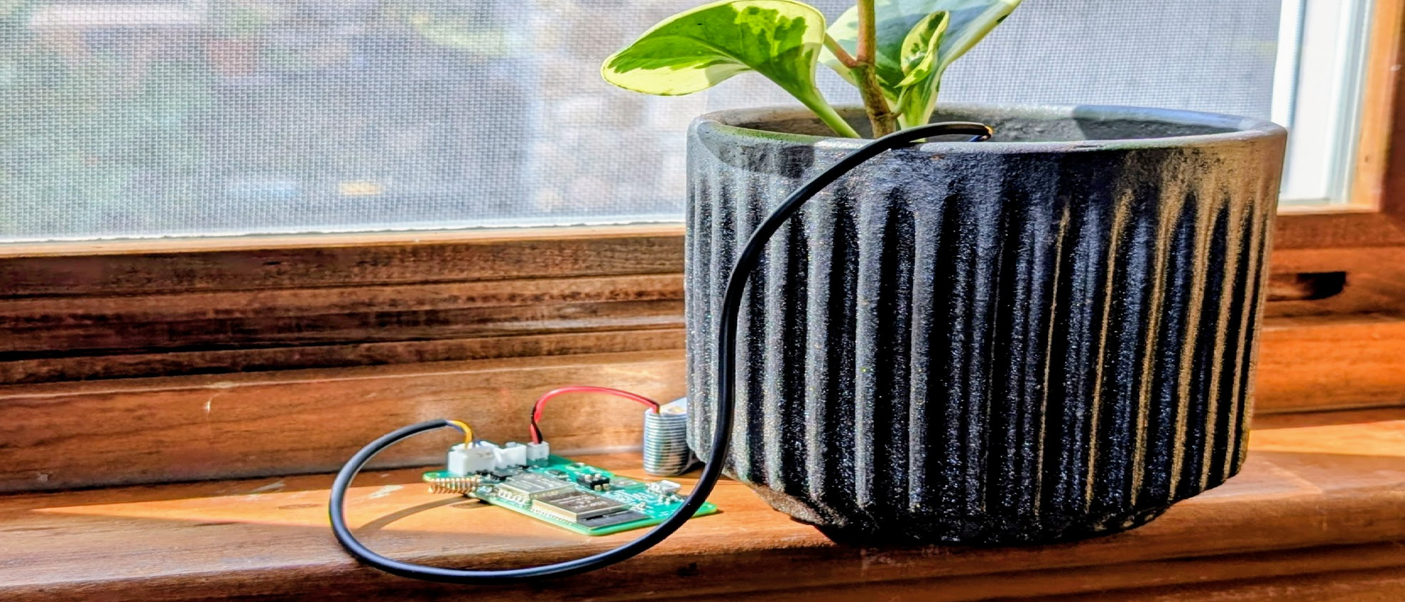
Overview
The Garden133 system monitors soil moisture in a yard or garden. After a number of attempts, I was excited to have built devices that live in the garden for months, powered by batteries and recharged by solar panels. The Garden133 Hardware blog post describes the hardware design circa 2025, and in particular the safe management of a lithium battery. Although the devices worked well, a week of cloudy days left them in danger of losing power. Also, I found that if a battery was not sufficiently charged at startup, the device might never start communicating. I suspected a spiraling boot-brownout-reboot cycle.
This year, I decided to find and address the power issues on these devices. I first designed board v7.0 to switch off the moisture sensor during sleep. Then, after an AI-assisted schematic review uncovered deeper flaws in the solar load-sharing circuit, I made board v8.0 to fix the diode and voltage regulator (and to update the radio module). This post describes the main power-system problems I found, and their solutions across these board revisions:
- Moisture Sensor Drain: While the ESP321 was in deep sleep and the LoRa2 radio was off, the capacitive soil moisture sensor3 continued to draw power. Without solar recharging, instead of lasting for close to a month, the battery lasted less than a week.
- Potential Brownouts at Startup and at Dusk: I selected an ultra-low forward-voltage
Schottky diode4 (
UPS115UE35) so that the system would function on solar power when sunlight was dim. This was a mistake. It allowed battery energy to leak at night, and could hold the battery MOSFET6 partially off at dusk. - Communication Brownouts: I found that if I sent too many LoRa packets in rapid
succession (or at least without pausing—LoRa is never really rapid), my board
could brown out.
I initially solved this in software by waiting a few seconds between packets during the
initial transmission of the board self-description.
On the hardware side, I had chosen a 300 mA voltage regulator (
NCP1147) which was insufficient for peak current spikes, particularly in debug mode where Wi-Fi communication is also active.
(In an upcoming follow-up post, I will cover two unexpected mysteries discovered while bringing up the v8.0 board, including a destructive TP40568 CMOS latch-up9 bug and a hidden deep-sleep drain on the new LoRa module.)
This post is sponsored by PCBWay, who generously manufactured a couple of generations of PCBs at no cost to me to help with this post. As always, the boards were simple to order, produced quickly, and performed exactly as designed.
Controlling Power to the Capacitive Moisture Sensor
The Capacitive Moisture Sensor Drains the Battery
The plot below shows a simple test of the 2025 Garden133 v6.2 board running on battery power.
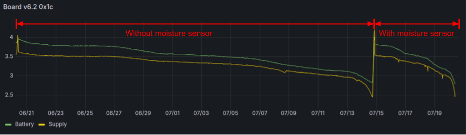
Without a moisture sensor, just waking and sending LoRa packets every 5 minutes, a fully charged battery lasted 24.5 days. After connecting a moisture sensor, the recharged battery lasted only 5.5 days. Because the entire purpose of the device is to monitor soil moisture levels, this was a critical difference.
Even though the ESP32 and LoRa radio spent almost all of their time in deep sleep drawing microamps,
the capacitive moisture sensor remained continuously powered from the +3.3V rail, drawing
roughly 4 to 5 mA around the clock.
Using component datasheets and schematic resistor values, the plot below estimates the board’s baseline current while sleeping at around 90 µA. Most of the time, when the board is sleeping, the moisture sensor is thus using 50 times more power than the rest of the device.
The next section shows how board v7.0 solved this problem, shutting off power to the moisture sensor when the board sleeps. As shown below, this lowers the expected total power used by the board over a full day, including both when the board is awake and asleep, by a factor of 10.
High-Side MOSFET Switching: Only Power the Moisture Sensor When Using It
An easy win for battery life is to power the moisture sensor only when needed.
To cut power to the sensor during sleep, I added a high-side switch on the sensor’s +3.3V
supply.
A GPIO pin controls power to the sensor.
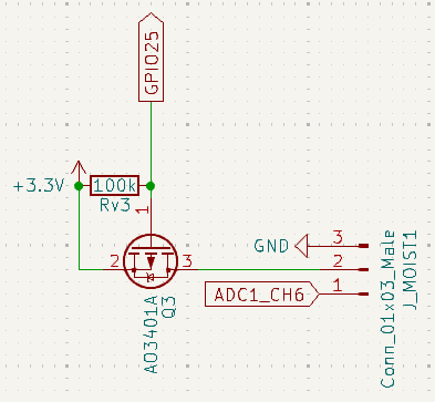
It is important to use a high-side switch rather than switching the ground line. Low-side (ground) switching on an analog sensor is dangerous: when the ground path is opened, the sensor board floats up to +3.3 V and can leak current backward through the analog signal wire into the ESP32’s ADC10 input pin.
An AO3401A11 P-channel MOSFET (Q3) serves very well for this role:
- BOM12 Consolidation: The board already uses an
AO3401A(Q2) in the solar load-sharing circuit, so it adds zero new part types to the pick-and-place setup. - Low Gate Threshold & On-Resistance:
With $V_{GS(\text{th})}$ around -0.7 V to -1.3 V, setting
GPIO25LOW brings $V_{GS}$ to -3.3 V, driving the MOSFET to full saturation. With $R_{DS(\text{on})}$ below 60mΩ, current flows to the moisture sensor with negligible voltage drop. - Deep-Sleep Isolation: A 100 kΩ pull-up resistor (
Rv3) between the gate and+3.3VholdsQ3firmly OFF while the ESP32 is in deep sleep andGPIO25is high-impedance.
Sensor Settling Time: Pause Before Reading the Moisture Sensor
I figured it would take some time for the moisture sensor to stabilize after it was first powered on. When the new v7.0 board arrived from PCBWay with MOSFET power control for the moisture sensor, I experimented with how long to wait. I found that if I sampled the ADC too quickly, the moisture reading was artificially high.
The capacitive moisture sensor outputs an analog voltage that is inversely proportional to
moisture: drier soil produces a higher voltage, and wetter soil pulls the voltage down.
To see what was happening right after power-on, I created an experimental version of the
Garden133 firmware to record the sensor output at high speed.
In developer mode, Garden133 runs a Wi-Fi web server, so I registered a special HTTP endpoint
(/api/moisture/trace) to trigger a capture and download the recorded trace as a CSV file.
When triggered, the firmware turns the moisture sensor off for 3 seconds to fully
discharge its onboard capacitors, switches power on at $t = 0$, then samples the ADC every
5 ms for 1.5 seconds.
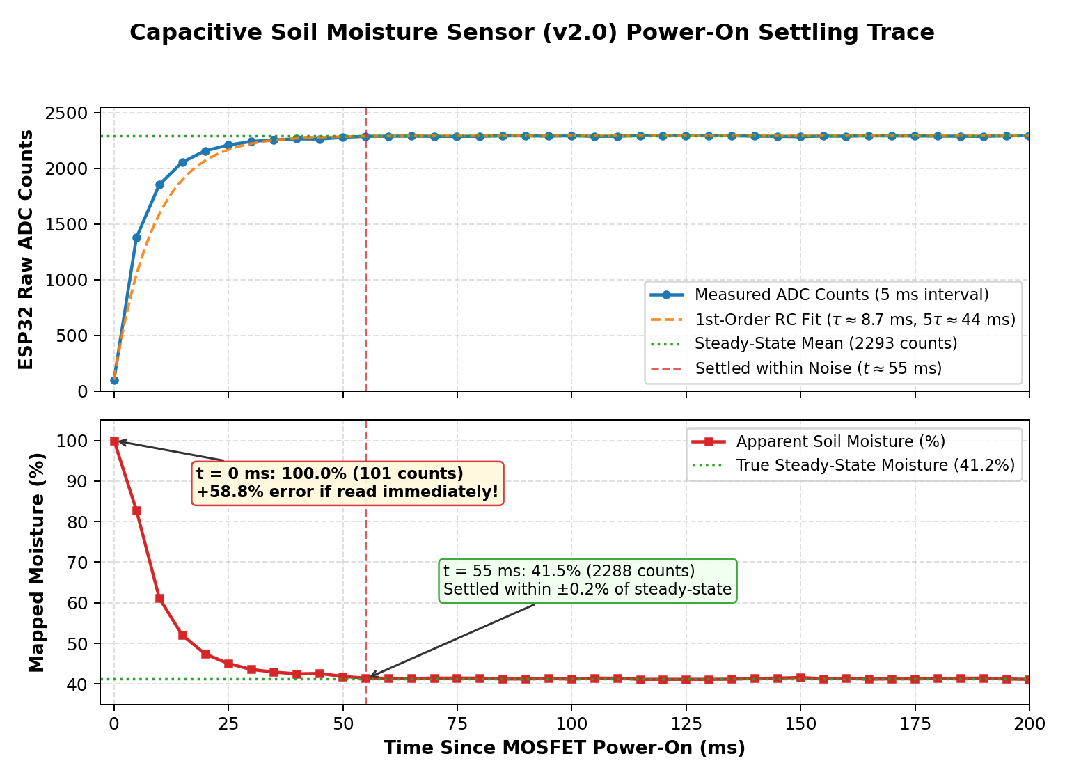
The readings follow the same kind of first-order $RC$ charging curve13 we saw for the thermal decay of the cooler in Dough133 Control, though much faster. For the moisture sensor, the effective time constant $\tau$ is about 8.7 ms, reaching 99% of its steady-state value ($5\tau$) at roughly 45–55 ms (potentially slightly longer when the probe is buried in wet soil with longer cabling).
When Garden133’s ESP32 powers on or wakes from deep sleep, it schedules
the moisture reading using a non-blocking state machine (with og3::Tasks14):
- In
setup(): Turn on moisture sensor power immediately at boot ($t = 0\text{ ms}$) by drivingGPIO25LOW. - Concurrent Initialization: While the moisture sensor settles during a conservative 100 ms delay, the ESP32 concurrently initializes SPI15, the LoRa radio, I2C16, and the SHTC317 sensor.
- Cold-Boot Description Sequence: On first boot, the firmware keeps the moisture sensor off while sending sensor description packets every 15 seconds via LoRa (see Design of a custom, low-power radio protocol), waits 15 seconds after the final description packet, powers on the moisture sensor ahead of the reading, transmits the first telemetry packet, and enters deep sleep.
- Low-Voltage Guard: Experiments show that moisture readings are unreliable when the
supply voltage ahead of the 3.3V LDO18 drops below 3.2V (where the 3.3V LDO is in
dropout, pulling the
+3.3Vrail down with it). In this case the ADC reading is still recorded for diagnostics, but excluded from the filtered soil moisture value.
With this improvement, my initial test showed that a Garden133 v7.0 board running purely on battery power could monitor soil moisture for just over a month: up from less than a week.
Diode Selection, Power Loss Analysis, and Preventing ESP32 Brownouts
AI can be a huge help to the largely self-taught electronics hobbyist like me. After testing the v7.0 board, I asked Gemini to review the power system schematic. It quickly identified several subtle circuit flaws. I realized I needed another spin of the board design before I could write this post! PCBWay graciously agreed to supply the redesigned boards.
As detailed in the first hardware post, Garden133 uses a load-sharing (power-path) circuit ahead of the TP4056 charger so that solar power can simultaneously supply the board and charge the Li-ion battery without confusing the TP4056’s charge-termination current detection:
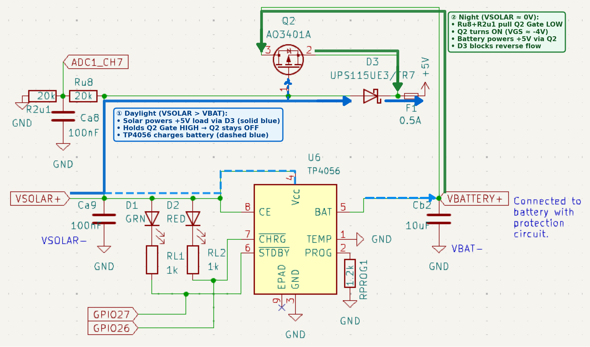
The Low-$V_F$ Schottky Diode Mistake
When designing v6.2, I worried about the voltage drop across diode D3 during periods of
dim sunlight.
Moisture readings become unreliable when the supply voltage to the LDO is low, and I
didn’t want the voltage drop across D3 to cause the system to struggle.
I picked the UPS115UE3/TR7 Schottky diode because it has an ultra-low forward voltage drop
($V_F$) of about 0.22 V at load currents of 100–200 mA.
This resulted in two notable problems.
Problem 1. Reverse Leakage: Why Low Forward Drop Causes Battery Drain at Night
I didn’t realize that low forward drop comes at a cost. It is achieved by a lower metal-semiconductor barrier height, causing reverse leakage current $I_R$ (current flowing the “wrong way”, backward through the diode) to increase exponentially. Reverse leakage current roughly doubles for every 10°C rise in temperature.
- While a standard Schottky ($V_F$ around 0.36 V) leaks 0.5 to 2μA at room
temperature, the
UPS115UE3leaks 50 to 200 μA at 25 °C and up to 1–3 mA in a hot summer enclosure (40 °C–60°C). - During the day, saving 0.14V when a 3 W solar panel is producing surplus power makes very little difference.
- At night, however, any current leaking backward from the battery through
D3drains the battery, drawing more power than the sleeping ESP32.
Problem 2. Dusk Gate Pull-Up: How Reverse Leakage Can Starve the ESP32
As important as the energy loss itself is where that reverse leakage current goes,
and what it does to P-MOSFET Q2 at sunset.
Remember that Q2 only turns on to connect the battery when its gate (VSOLAR+) drops well
below the battery voltage (~3.8 V).
If reverse leakage through D3 holds VSOLAR+ above ~2.6 V after dark, Q2 never fully
turns on.
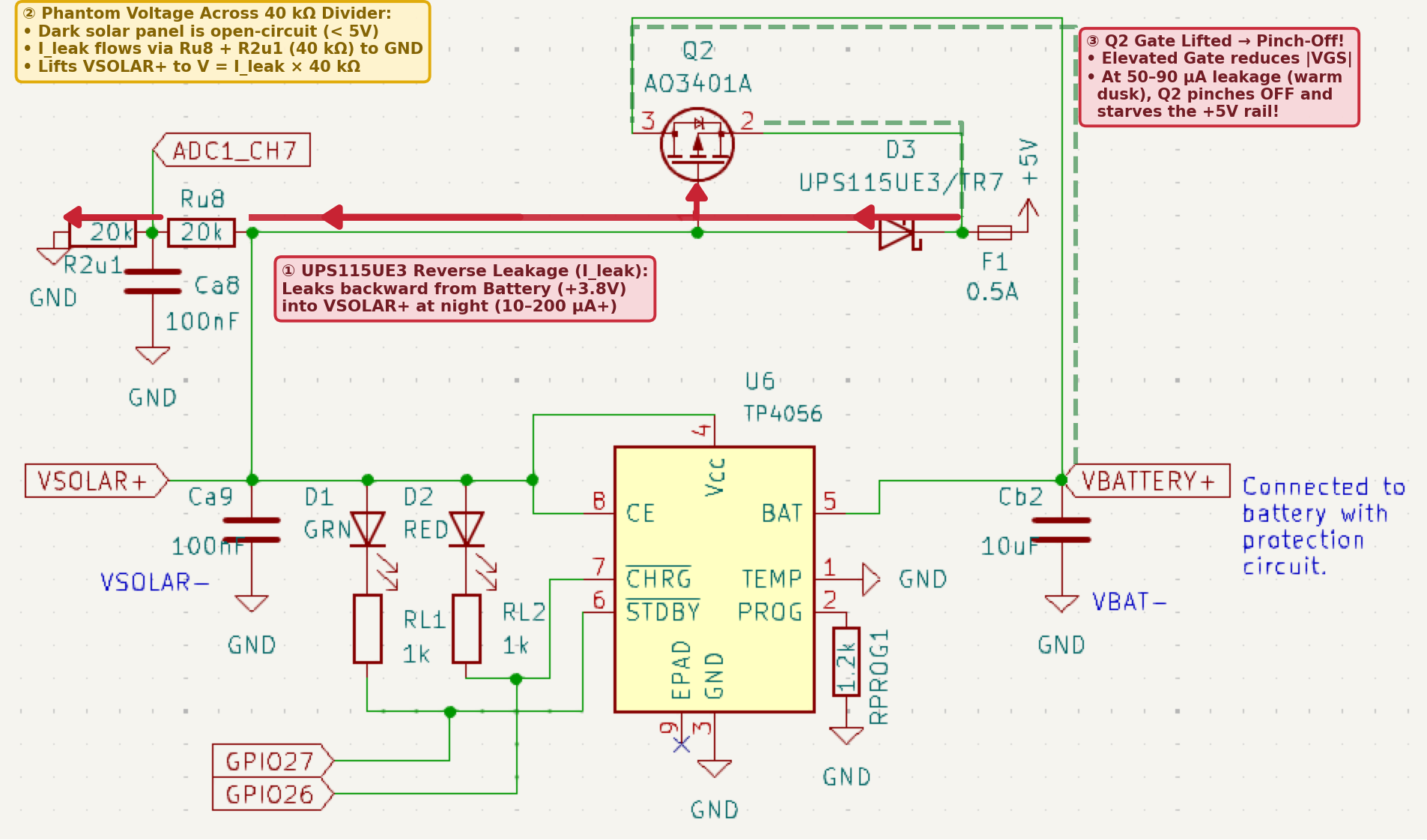
There are three paths this current might take to ground, as modeled in the temperature plot below:
- The 40 kΩ voltage divider.
The current through the voltage divider ($I_{\text{div}}$) is plotted below as the green
dashed curve.
This current is known because we measure
VSOLAR+via ADC: $I_{\text{div}} = V_{\text{solar}} / 40\text{ k}\Omega$. By raisingVSOLAR+this current could keep the board from switching to battery power. The condition under which this is expected to occur is shown below in red, where $I_{\text{div}} \ge 65\ \mu\text{A} \Rightarrow V_{\text{solar}} \ge 2.6\text{ V}$: when the temperature is above ~34 °C (94 °F). - The TP4056’s
VCCandCEpins. Current may leak to ground through these pins depending on temperature. This component of the battery-drain acrossD3is unknown: it cannot be sensed by the Garden133 board. Its potential range is shown below as the shaded orange band up to the brown upper bound. - The solar panel. At nighttime, this acts as a series of diodes that effectively block reverse current. We don’t expect current to flow through the panel.
On a very hot evening, above ~34 °C (94 °F), power from the battery could be blocked as solar power diminishes, starving the 3.3V regulator and trapping the ESP32 in a brownout reset loop.
Replacing the Schottky Diode with a MAX40200 Ideal Diode
Options to deal with the problem diode included replacing it with a low-leakage Schottky diode, replacing it with an ideal diode, and replacing both it and the MOSFET switch with a power-MUX chip.
| Component | Type | Typical Forward Drop (@ 150 mA) | Reverse Leakage (@ 4V, 25°C) | Package | Notes |
|---|---|---|---|---|---|
| UPS115UE3/TR7 | Ultra-Low $V_F$ Schottky | 220mV | 50–200μA (mA when hot) | DO-216AA | In board v6.2. High leakage; dusk gate pinch-off risk. |
| PMEG4010ER19 | Low-Leakage Schottky | 360mV | 0.5–2.0μA | SOD-123W | Simple passive fix; $100\times$ lower leakage. |
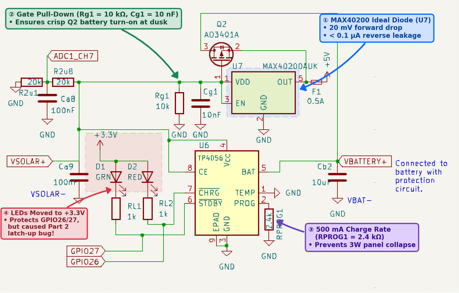
| MAX40200AUK20 | Single Ideal Diode IC | 20 mV (85 mΩ) | < 0.1μA | SOT-23-5 | Replaces D3, keeps Q2 hysteresis; easy to hand-solder. |
| TI LM6620021 | Dual Auto Power MUX | 6 mV (40 mΩ) | < 0.1μA | SOT-583 (0.5 mm) | Replaces both D3 & Q2, but risks twilight chattering. |
I chose the MAX40200AUK ideal diode.
It provides a small forward voltage drop, while avoiding the more difficult form factor
and potential rapid switches between power sources that could occur with the power MUX.
For circuits which may either be powered by an external supply or an internal battery, a
dual-input power multiplexer like the TI LM66200 can be a good choice.
For my application, where the external power is a solar panel which will gradually lose
voltage in the evening and gain voltage in the morning, I was worried that the
zero hysteresis22 nature of the chip would be problematic.
When the voltage of one source (solar or battery) starts to exceed the voltage of the other, the power multiplexer switches its source to that with the higher voltage. Supplying power to the circuit will cause this source’s voltage to fall, however, potentially triggering the multiplexer to switch back to the original source. This switching cycle could potentially happen thousands of times a second.
Eliminating Communication Brownouts on v8.0
Along with replacing D3 with the MAX40200, I made four additional changes on the v8.0 board to
prevent brownouts during LoRa and Wi-Fi transmit bursts:
- Stiffer Gate Pull-Down on
Q2: Added a dedicated 10 kΩ pull-down resistor (Rg1) and 10nF bypass capacitor (Cg1) onQ2’s gate for a crisp battery switchover. - Upgraded 3.3V Regulator & Bulk Capacitors: Replaced the 300 mA
NCP114with a 600 mAAP2112K-3.323 LDO (U3) and 10 µF bulk capacitors. - Moving the Power Switch Out of the Current Path: On v6.2/v7.0, the main
+5Vsupply rail ran physically through a DIP switch (SW1), adding contact resistance during 400mA radio spikes. On v8.0,+5Vroutes directly to the LDO, and the switch simply toggles the microampLDO_ENcontrol pin. - Matching the TP4056 Charge Rate to Small Solar Panels (
RPROG1): ChangedRPROG1from 1.2 kΩ (1.0 A charge rate) to 2.4 kΩ (500 mA), so small 2.5W–3W solar panels aren’t pulled below the charger’s 3.8 V dropout threshold into on/off “motorboating” cycles.
Field Telemetry Comparison: Board v6.2 vs. Board v8.0
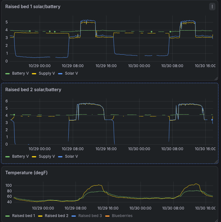
The Grafana24 plot below compares live voltage and temperature telemetry over two days from Raised bed 1 (top, v6.2 board) against Raised bed 2 (middle, v8.0 board with ideal diode), alongside onboard SHTC3 temperature readings (bottom). The predictions made via the circuit analysis above are nicely demonstrated by this garden data.
Phantom Nighttime “Solar” Voltage
For the v8.0 board, “Raised bed 2” (middle plot), we can see that the ideal diode is
working as intended.
The blue Solar V trace drops straight to 0.0V at sunset on both nights regardless of
temperature: reverse leakage is eliminated.
The data in the top plot, “Raised bed 1,” is from a v6.2 board.
The blue trace, “Solar V,” shows the voltage from the D3 leakage current which goes
through the 40 kΩ divider.
The current through the divider keeps the voltage from reaching zero, and
we can see how the Schottky reverse leakage increases with temperature.
Both nights, we can see the voltage from the leakage current drop from dusk to pre-dawn as temperature drops, and current is higher during the warmer night (10/29-10/30).
| Night | Temperature (dusk –> low) | Voltage range | Current across 40 kΩ divider |
|---|---|---|---|
| 10/28-29 | 11.0°C –> 6.1°C (52°F –> 43°F) | 0.65V –> 0.45V | 16.2µA –> 11.2µA |
| 10/29-30 | 18.3°C –> 12.2°C (65°F –> 54°F) | 0.95V –> 0.72V | 23.8µA –> 18.0µA |
Using the rule of thumb that reverse leakage current roughly doubles for every 10°C rise in temperature, we expect the ratio of end-of-night current for the two nights, with a temperature difference between them of 6.1 °C (12.2°C vs. 6.1°C), to be:
With this diode, and this temperature range, the doubling constant is closer to 9.5, so
The measured ratio matches this closely:
For VSOLAR+ to reach the 3.0–3.6V range where Q2 blocks battery power,
roughly 4 times the observed leakage, the dusk temperature would need to be
35°C–40°C (95°F–105°F).
This is unlikely here in New England, but is a conceivable danger elsewhere.
Plotting the estimated reverse leakage range over time across those two nights shows that even in cool October weather, nighttime diode leakage exceeds the ~11.5 µA sleep draw of the ESP32, LoRa, and SHTC3 chips combined. It is 11–31 µA, peaking at 24–46 µA at dusk on Night 2.
Daytime Forward Voltage Drop Eliminated
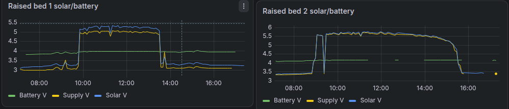
On Raised bed 1 (v6.2), whenever the board runs on solar power (midday peaks and
morning/afternoon shoulders), there is a clear vertical gap between the blue Solar V trace
and the yellow Supply V trace underneath it due to the 220mV forward drop of the
Schottky diode.
On Raised bed 2 (v8.0), these traces are nearly indistinguishable because the
MAX40200 ideal diode drops a tenth as much (20mV).
This helps keep the supply voltage above the 3.2V threshold, where moisture sensor readings are reliable, even when the panel is not in direct sunlight.
Side Note: Switching to a Newer LoRa Module
When looking to replenish my supply of HopeRF RFM95W modules I realized they are somewhat
obsolete.
So along with the power system upgrades and fixes, I changed the Garden133 v8.0 board to use
the Ai-Thinker Ra-01SH25.
The Ra-01SH uses the newer Semtech SX1262 chip, is slightly smaller, easier to buy, and
less expensive.
Software support was simple because I had already switched my
og3x-lora library to use
RadioLib, which supports both modules.
Conclusion
Addressing these three power bottlenecks dramatically improved the performance of the Garden133 sensor nodes:
- Powering the soil moisture sensor only when needed extended pure-battery runtime from less than a week to over a month.
- Replacing the ultra-low $V_F$ Schottky diode with an ideal diode eliminated the temperature-dependent nighttime reverse leakage that further sapped battery runtime, and which could cause a brown-out at dusk on a very hot day.
- Upgrading to a 600 mA LDO eliminated the danger of brownout during radio transmissions.
However, getting the first v8.0 boards working on the bench wasn’t quite that simple.
In an upcoming “Part 2” post, I will walk through unexpected design flaws discovered during v8.0
bring-up.
These include a well-intentioned change that triggered a short inside the TP4056 charger IC,
and a hidden deep-sleep current drain on the new SX1262 LoRa module.
As always, the updated KiCad26 schematics, PCB27 layout, and firmware are available in the Garden133 GitHub repository.
References
-
ESP32: a family of microcontrollers made by Espressif Systems, and the successor to the ESP8266 microcontroller. ↩︎
-
LoRa (the name stands for “long range”) is a proprietary radio communication technique (Wikipedia, Semtech). It is specialized for long range, low bandwidth, low power radio communication for Internet of Things (IoT) applications. ↩︎
-
Capacitive moisture sensor (from Amazon). ↩︎
-
A Schottky diode is a metal–semiconductor junction diode with a lower forward voltage drop and faster switching action than a standard silicon PN-junction diode, at the trade-off of higher temperature-dependent reverse leakage current (Wikipedia). ↩︎
-
UPS115UE3/TR7 1A, 15V ultra-low forward voltage ($V_F \approx 0.22\text{ V}$) Schottky rectifier. ↩︎
-
MOSFET. The metal–oxide–semiconductor field-effect transistor (MOSFET) has the ability to change conductivity with the amount of applied voltage, and can be used for amplifying or switching electronic signals (Wikipedia). ↩︎
-
NCP114ASN330T1G $300\text{ mA}$ low-dropout linear voltage regulator designed for battery-powered applications. ↩︎
-
TP4056 1A standalone linear lithium-ion battery charger IC with thermal regulation and open-drain status indicator pins. ↩︎
-
CMOS latch-up is the inadvertent creation of a low-impedance short circuit between power and ground caused by triggering a parasitic four-layer PNPN silicon-controlled rectifier (SCR) structure inside a CMOS integrated circuit—commonly triggered when voltage is applied to an I/O pin while the chip’s power supply ($V_{\text{CC}}$) is unpowered (Wikipedia, TI Application Report). ↩︎
-
ADC. An analog-to-digital converter (ADC, A/D, or A-to-D) is a system that converts an analog signal, such as a sound picked up by a microphone or light entering a digital camera, into a digital signal (Wikipedia). ↩︎
-
AO3401A P-channel MOSFET: a low-threshold ($V_{GS(\text{th})} \approx -0.9\text{ V}$), low on-resistance ($50\text{–}85\text{ m}\Omega$) surface-mount transistor well-suited for $3.3\text{ V}$ logic-level switching. ↩︎
-
Bill of Materials (BOM). A list of components needed to assemble some end product. ↩︎
-
The $RC$ time constant ($\tau = R \times C$) is the time required for a resistor-capacitor circuit to charge to $\approx 63.2%$ ($1 - e^{-1}$) of its final step-change voltage, reaching $\approx 99.3%$ after $5\tau$ (Wikipedia). ↩︎
-
og3is my C++ utility library for ESP microprocessors, published on GitHub. ↩︎ -
Serial Peripheral Interface (SPI) is a de facto standard, with many variants, for synchronous serial communication, used primarily in embedded systems for short-distance wired communication between integrated circuits (Wikipedia). ↩︎
-
$\text{I}^2\text{C}$ (Inter-Integrated Circuit) is a synchronous, multi-controller, multi-target two-wire serial communication bus widely used to attach low-speed peripheral ICs and sensors to microcontrollers (Wikipedia). ↩︎
-
An SHTC3 module is a temperature and humidity sensor that communicates with a microprocessor using I2C (AliExpress) (Datasheet). ↩︎
-
A low-dropout regulator (LDO regulator) is a DC linear voltage regulator that can operate even when the supply voltage is very close to the output voltage (Wikipedia). ↩︎
-
PMEG4010ER 40V, 1A low-leakage Trench MEGA Schottky barrier rectifier. ↩︎
-
MAX40200 1A ideal diode IC in a compact
SOT-23-5package that regulates an internal P-FET to achieve a $\sim 20\text{ mV}$ forward voltage drop at light loads and $< 100\text{ nA}$ reverse leakage. ↩︎ -
TI LM66200 dual-input ideal diode power multiplexer (Power MUX) that automatically selects the higher-voltage input supply with $40\text{ m}\Omega$ on-resistance. ↩︎
-
Hysteresis in electronic comparators and switches is the separation between turn-on and turn-off voltage thresholds that prevents rapid oscillation (“chattering”) when an input signal hovers near the switching threshold (Wikipedia). ↩︎
-
AP2112K-3.3 CMOS low-dropout (LDO) linear voltage regulator capable of supplying up to $600\text{ mA}$ with a low $250\text{ mV}$ dropout voltage and $55\ \mu\text{A}$ quiescent current. ↩︎
-
Ai-Thinker Ra-01SH LoRa radio module based on the Semtech SX1262 transceiver. ↩︎
-
A printed circuit board (PCB) connects electrical components together to make an electrical circuit. It is a laminated sandwich structure of conductive and insulated layers. ↩︎