Plant133: A DIY Automatic Indoor Plant Watering System
Posted on November 18, 2023 • Last modified on September 19, 2026 • 13 min read • 2,638 words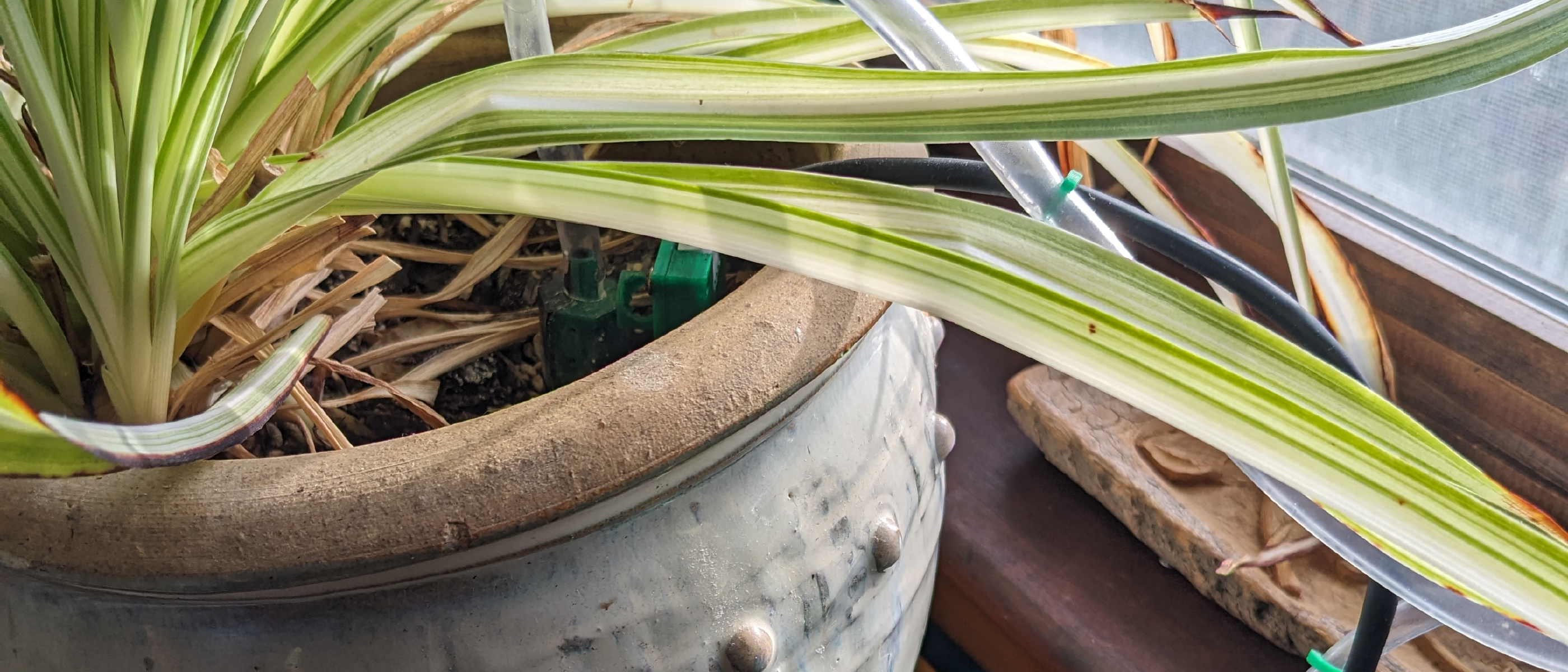
Automating indoor plant watering sounds simple until you consider soil hydrology and Murphy’s law. If you naively pump water until a soil sensor detects moisture, diffusion delay will cause you to over-saturate the root zone and drown your plant. Worse, if the soil sensor fails, stops making good contact with the soil, or is removed from the soil for whatever reason, you might pump the reservoir dry, overflow the pot or its base, damage the pump, and even damage your house. Plant133 is an automated indoor watering device powered by an ESP32 and a custom PCB that solves this using a closed-loop pulsed watering cycle, daily watering limits, and adaptive digital signal filtering.
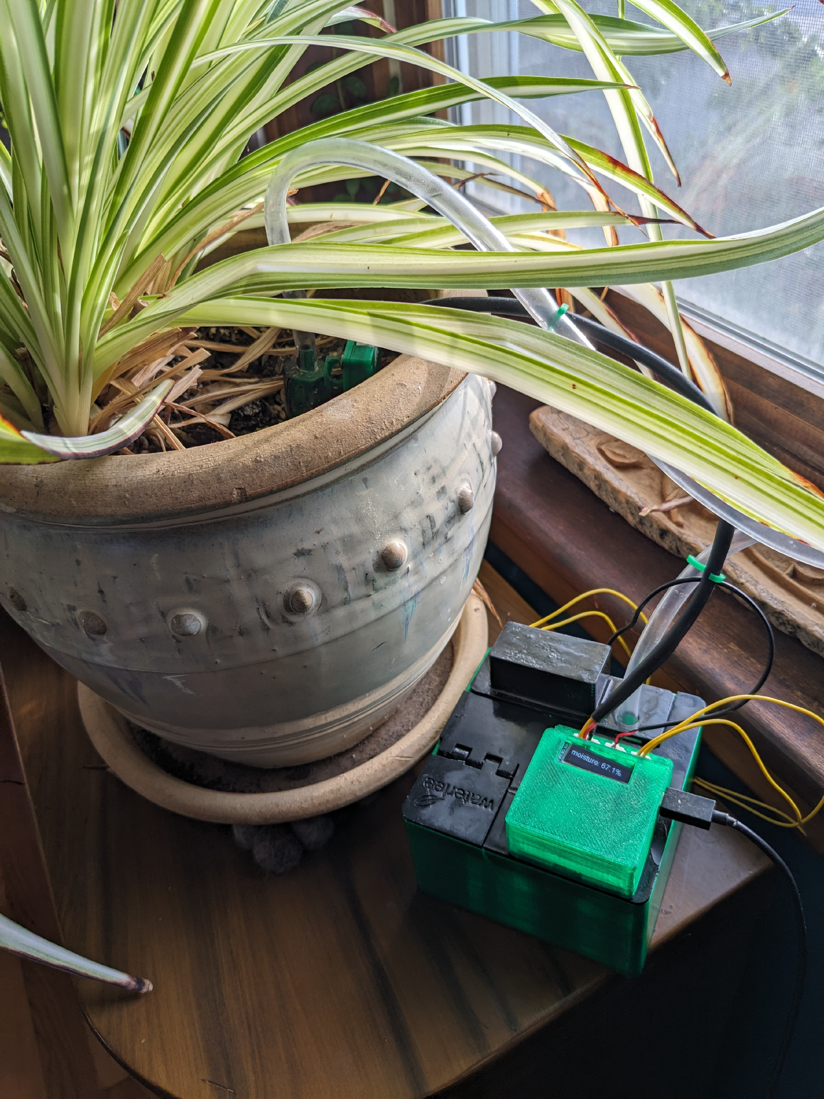
The system is designed for unattended operation: keeping soil moisture precisely within a target window, protecting the submersible pump from running dry, and reporting telemetry to a smart home system.
This post covers the initial hardware design, closed-loop watering logic, and physical construction. Later posts expand on lessons learned from years of real-world use:
- Plant1337: Next-Generation Multi-Plant Watering : Scaling the architecture up to monitor and water multiple independent plants from a single controller.
- Improving Reliability & Lessons Learned : A post-mortem on sensor degradation, pump longevity, and which hardware components failed over time.
- Building a Modern Web Interface with Svelte : Replacing basic embedded forms with a reactive, modern dashboard running directly on the ESP32.
System Architecture
Rather than a simple threshold switch, Plant133 is built around a closed-loop control and monitoring pipeline:
- Pulsed Closed-Loop Control: A state machine runs short pump bursts followed by 15-minute diffusion pauses, giving water time to soak through the soil column before re-evaluating moisture.
- Adaptive Signal Filtering: Switches between a wide 5-minute smoothing kernel during active watering cycles to reject noise, and a fast tens-of-seconds filter during idle monitoring.
- Pump Run-Dry Protection: A mechanical float switch paired with a programmable 10-second runout budget allows the system to scavenge the bottom of the reservoir without running the pump dry.
- Custom KiCad PCB: Integrates a 5V-to-3.3V buck regulator, N-channel MOSFET motor drive with inductive flyback protection, and an I2C OLED diagnostic display.
- Production IoT Telemetry: Native Home Assistant MQTT auto-discovery, InfluxDB time-series logging, and push notifications when the reservoir needs refilling.
The Closed-Loop Watering Process
The primary challenge in automated watering is managing the delay between adding water at the surface and sensing that water at the root level. When Plant133 waters my spider plant, it maintains soil moisture between 65% and 75%, where 0% represents dry air and 100% represents immersion in a glass of water.
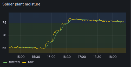
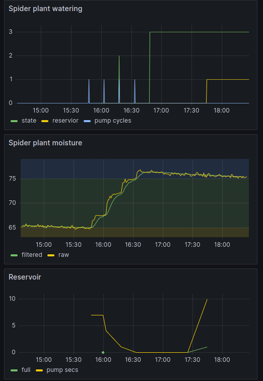
When the soil moisture drops below 65%, Plant133 initiates a sequence of watering pulses. The pump runs for a few seconds, followed by a (configurable) 15-minute wait state that lets moisture migrate naturally through the soil. This sequence creates the distinct stair-step pattern shown in the telemetry plot above: the raw sensor signal is plotted in yellow, while the real-time filtered value is shown in green. Watering halts as soon as the smoothed reading crosses the 75% upper limit.
This operational logic is governed by the state machine below:
There is one additional failsafe: a daily limit for pump cycles. Moisture sensor readings can be unreliable for a number of reasons: sensor failure, a broken wire or poor connector contacts, poor soil contact, or the sensor getting completely knocked out of the soil. In some of these cases, the moisture sensor reading will be detected as invalid and watering will be disabled. In other cases, the moisture reading might appear valid but never reach the desired value no matter how much water is pumped. If the reservoir has enough water, this can lead to all kinds of problems. Thus we limit the total number of watering cycles per day to a safe number, typically 4 or 5, to avoid damage to plant and house, and to detect and report the potential problem.
Hardware
Plant133 is designed to be made using inexpensive and easily obtainable hardware. This includes a pump, sensors, microcontroller, 3D-printed components, and a custom-designed circuit board. All printed components were designed using the OpenSCAD1 CAD package.
Sensors
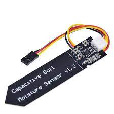
Plant133 has three sensors. Because this is a system for watering plants, the most important is the soil moisture sensor. This capacitive moisture sensor2 is reliable for a long time, especially if you seal its edges , is non-toxic, and works acceptably for this kind of application. See the YouTube video on the subject by Andreas Spiess.3 The sensor is powered by 5V, and has an analog output that can be read with the microcontroller used for this project.
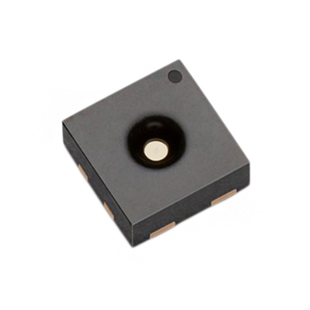
For reading temperature and humidity, the system uses a SHTC34 sensor.
This sensor performs well and is simple to interface with the microcontroller.
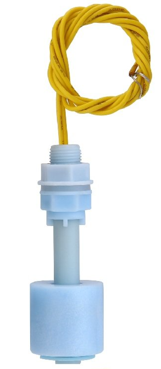
For detecting when the reservoir level is getting low, it uses a simple
float sensor.5
Actuator
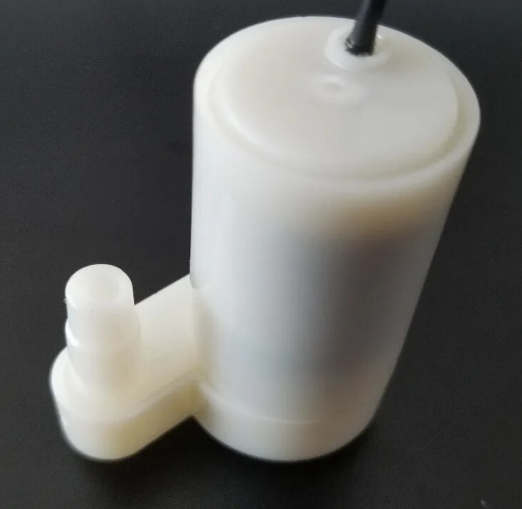
The system uses an aquarium pump6 to move water from the reservoir to the plant.
The vertical pump configuration has the intake hole on the bottom,
which allows use of almost all the water in the reservoir.
Water below the level of the intake cannot be used.
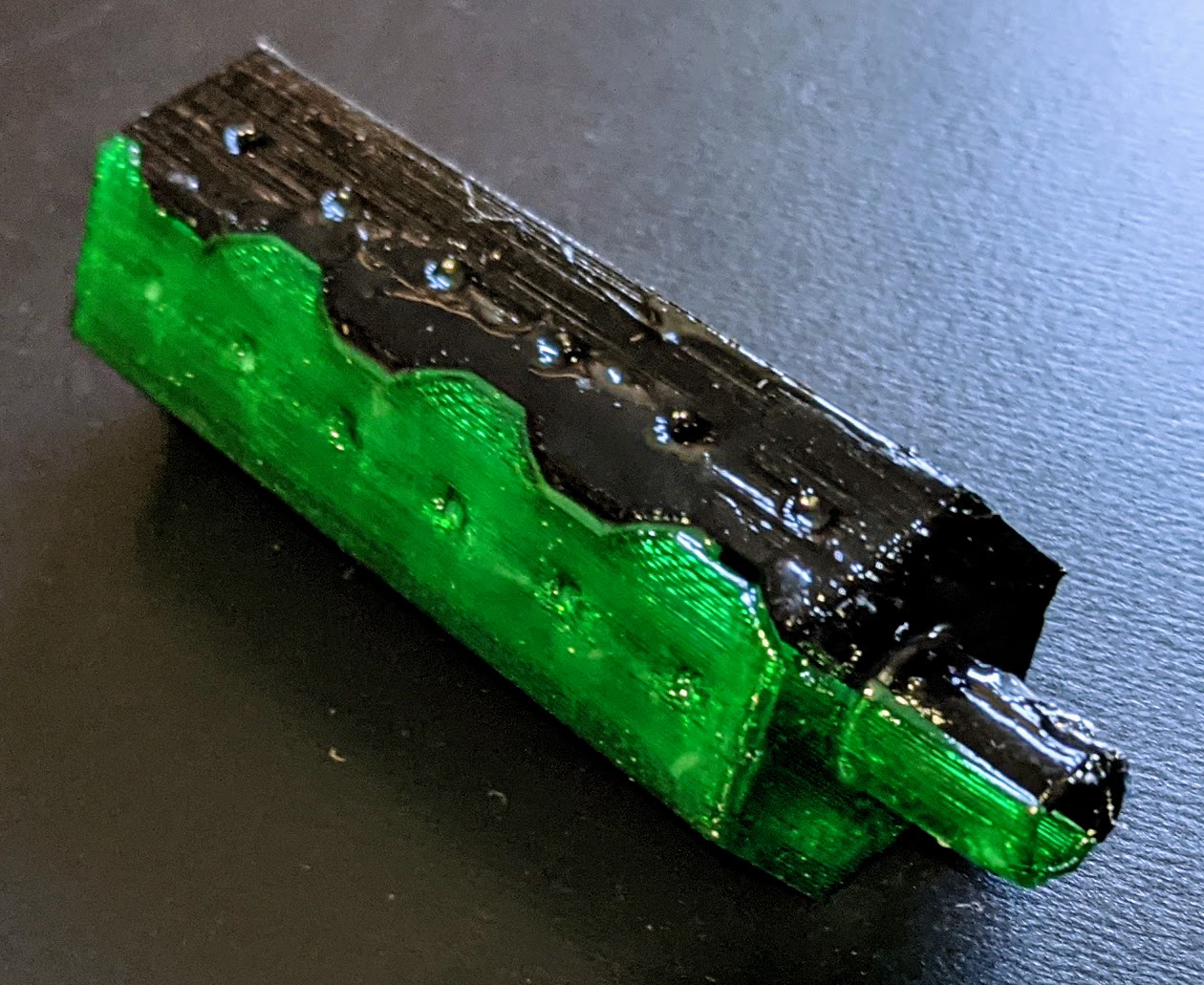
A printed spike inserted into the soil spreads the pumped water.
The spike is printed in two pieces, then connected together with the epoxy
coating which also makes the part waterproof.
Water reservoir
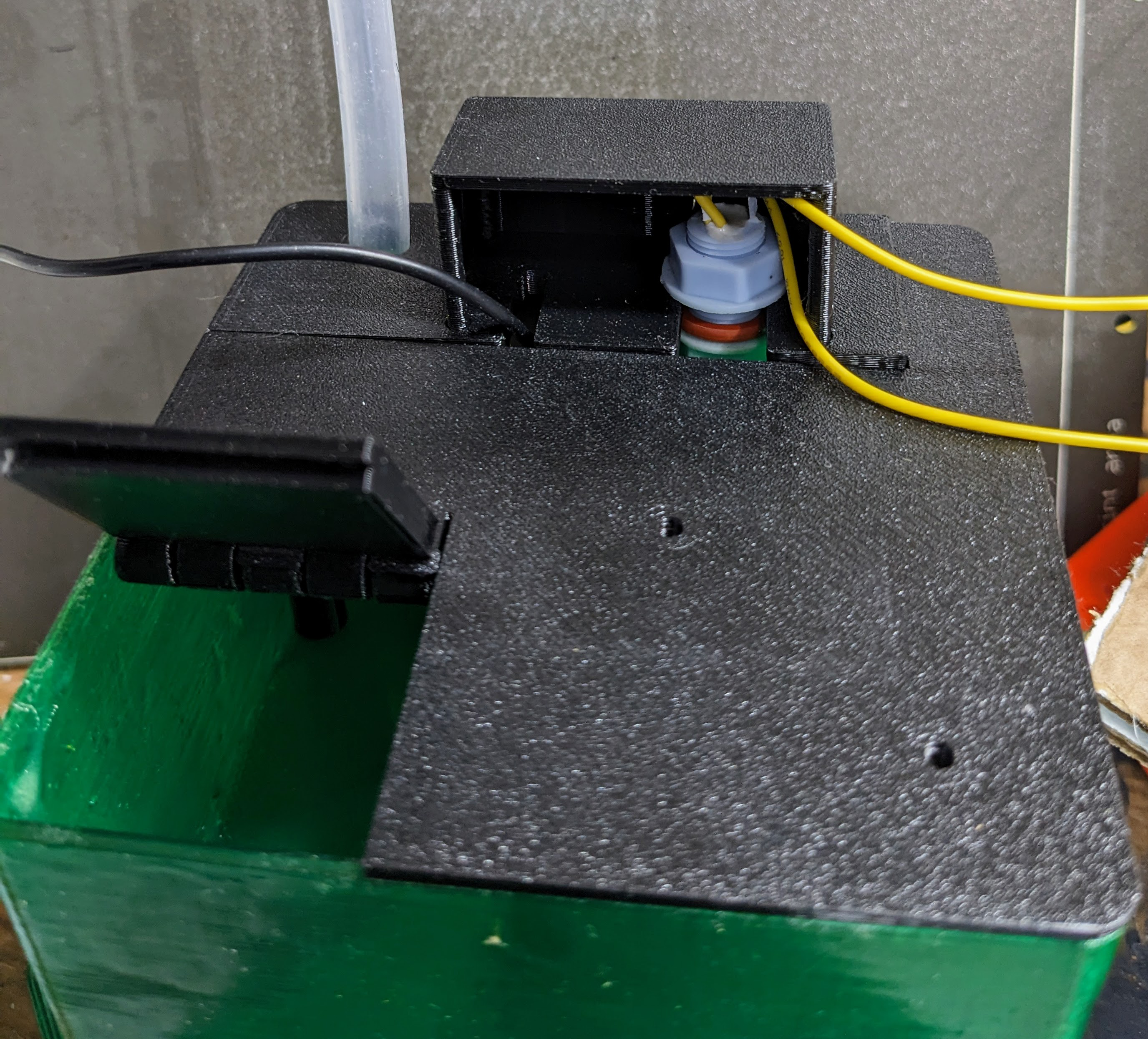
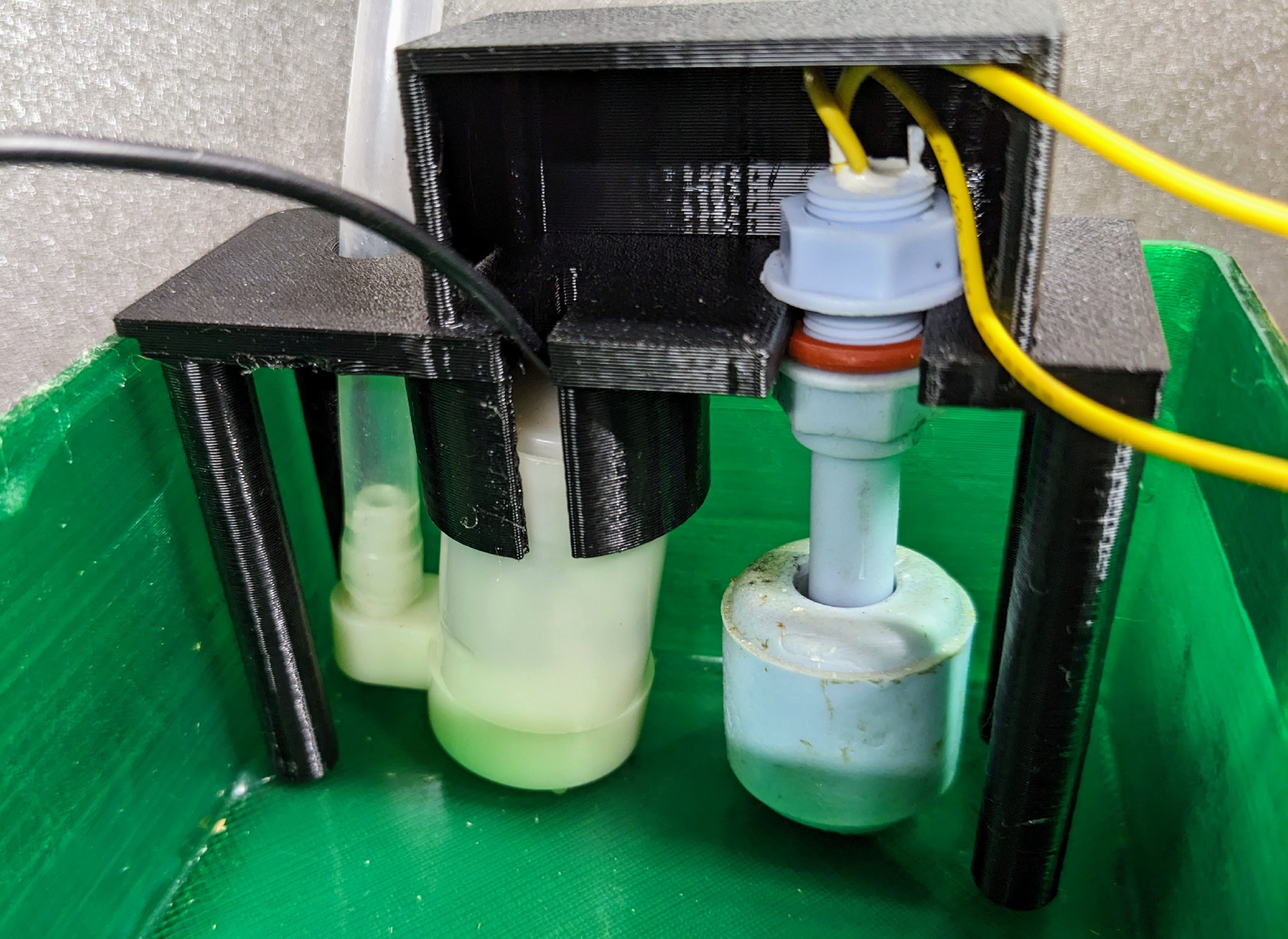
The reservoir, lid, and insert are printed with PETG filament, and coated with epoxy to make them waterproof.
Circuit board
Inside the EBox is the main circuit board.
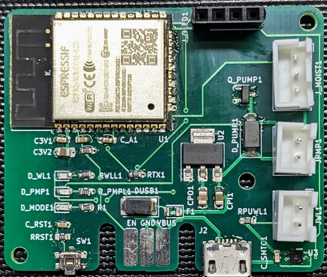
- Analog inputs which can read the moisture sensor,
- Digital inputs which can read the float sensor,
- Digital outputs which can control the pump and LED indicator lights,
- An I2C serial interface which can be used to talk to an OLED display and the temperature/humidity sensor,
- A serial interface which can be used to talk to a developer computer using a separate USB to serial board,
- Onboard flash storage which can be used for storing software and configuration settings, and
- A Wifi interface for talking to a web browser, and optionally to a MQTT broker for data-logging and control.
The ESP32 module is relatively inexpensive, and can be used with a large number of open source Arduino libraries for things like sensor interfaces, flash storage, web clients, and MQTT clients.
Wifi is important because it provides a way for users to set the watering parameters such as minimum and maximum soil moisture levels and the length of time the pump runs during a watering cycle. It also makes possible some methods to notify users to refill the reservoir.
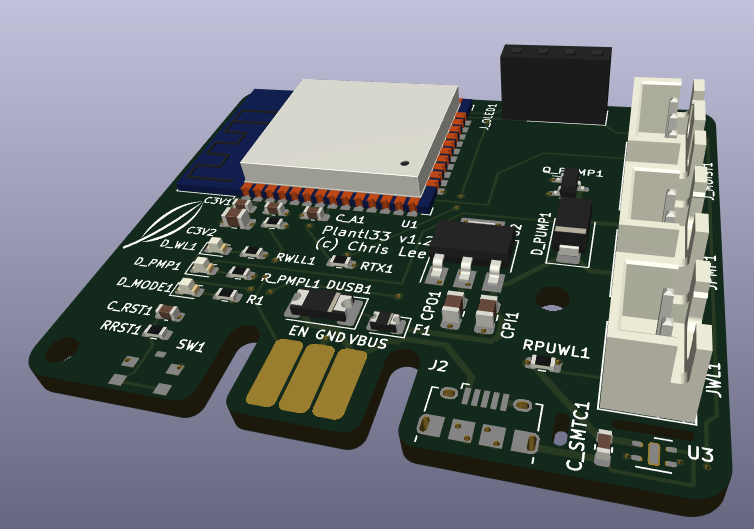
The circuit board provides connections from the microprocessor to connectors for the pump, moisture sensor, float sensor, and an OLED screen. It also has a USB micro jack for power, and an edge connector which can be used to attach an external USB serial adapter for reprogramming the CPU. The board has a MOSFET and fly-back diode for powering the pump motor, and a 3.3V voltage converter for powering the microprocessor. There is also the temperature/humidity sensor mounted near the connectors where it can be exposed to the air. LED indicator lights indicate the state of the reservoir sensor, pump power, and the watering state machine.
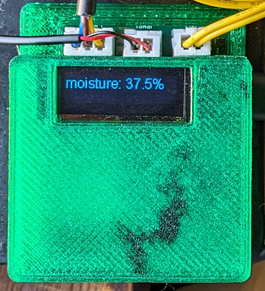
The circuit board was designed using the open source KiCAD7
package, and printed by JLCPCB.8
Software
Framework
The software for Plant133 is written in C++. I used the Arduino framework for developing software for the ESP32 because of the ease of finding documentation, examples, and libraries online. I used the PlatformIO9 development system because I wanted a command-line interface for building code and the ability to create libraries and projects with a number of source files.
Web interface
The code has a web interface for configuring a connection to a WiFi access point.
When no Wifi connection is configured, it starts as an access point with ESSID
“plant133” and no password.
A user can connect to it, and then press the “WiFi Configure” button to tell
it how to connect to an access point.
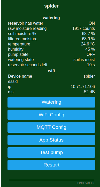
Once the device is connected to a WiFi server, it displays its IP address using its OLED screen so one can easily connect to it via a web browser on a computer that is connected to the same network.
The web interface can also be used to connect to a MQTT broker, and to set parameters for the plant watering system.
Configuration
A number of configuration parameters can be specified.
The minimum and maximum soil moisture levels for the plant can be set,
as well as the time to run the pump for each increment of watering.
A user can also calibrate the moisture sensor by setting the ADC readings
when the sensor is in the open air and when submerged in a glass of water.
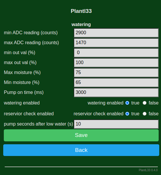
The web interface can also enable or disable the watering system, and enable or disable the reservoir water check. If the reservoir level is enabled, then after the water level sensor reads low-water (e.g., the float is at the bottom of its travel), the pump will run a total of a specified number of seconds, usually 10, and then watering is suspended until the water level sensor indicates that there is water in the reservoir again.
MQTT
For development and monitoring, it is useful for the system to communicate its inner state to the outside world. One useful way to do this for “Internet of Things” (IOT) devices is the MQTT protocol.[^MQTT protocol] The system state is sent periodically to an MQTT broker, where other systems can subscribe to updates. An example of this state information, encoded as a JSON string, is shown below.
{"reservoir":              "ON",
 "soil_moisture_raw":      1919,
 "soil_moisture":          68.60,
 "soil_moisture_filtered": 68.66,
 "temperature":            27,
 "humidity":               30.76,
 "pump":                   "OFF",
 "watering_state":         3,
 "pump_sec_left":          10}
Home Assistant
I run the Home Assistant[^Home Assistant] home automation system at my house.
The Plant133 system sends special MQTT messages to the broker which tells
Home Assistant about the available status information and how to use it.
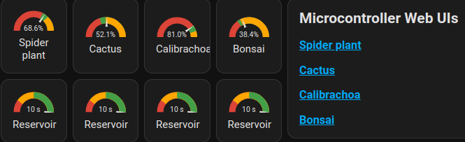
Home Assistant sends a notification to my phone when a reservoir needs refilling.
InfluxDB and Grafana
At my house, this data also goes to an
InfluxDB10 time series database for long-term storage and analysis.
The data can be displayed via InfluxDB’s built in graphing systems or using
a system like Grafana.11
An example Grafana plot showing the status of the system watering the spider
plant is shown here.
Conclusion
Plant133 has gone through a huge number of iterations. So far, it is working reliably in my house, but earlier versions have not worked well in other households due to reliability and lack of usability when not connected to Home Assistant. When something wasn’t working correctly, it was very difficult to detect and diagnose the problem. If mDNS was not available, it was tricky figuring out the IP address of the device to open its web interface. Improvements in the latest version, adding an OLED screen and various hardware and software updates, have taken it to the point where it is useful for other homes.
Please see my follow-up posts about the project:
- “Plant1337: A Next Generation DIY ESP32 Automatic Plant Watering System” describes the latest version of the device, which supports multiple plants,
- Improving Reliability for ESP32 Plant Watering Systems: Lessons from Plant133 reveals which components have most needed replacement over time and how I’ve tried to improve them.
- Building a Modern ESP32 Web Interface with Svelte and AI investigates modern web interfaces for embedded ESP32 devices, and shows a new interface I built for Plant133.
All software and hardware designs for the latest version of this projects are available at my GitHub repository under the very permissive MIT license.
References
-
OpenSCAD is an open source program implementing a programming language for building 3D models. It is a way to build models using solid modeling primitives. ↩︎
-
Capacitive moisture sensor ( from Amazon ). ↩︎
-
Andreas Spiess produces YouTube videos on sensors, radios, microprocessors, and electronics. ↩︎
-
An SHTC3 module is a temperature and humidity sensor that communicates with a microprocessor using I2C ( AliExpress ) ( Datasheet ). ↩︎
-
Aquarium pump ( from AliExpress ). The vertical pump orientation works best. ↩︎
-
JLCPCB is a company from which I ordered circuit boards designed using KiCAD. ↩︎
-
PlatformIO is an open source framework for compiling and uploading embedded software, and managing libraries used by this software. ↩︎