Custom DIY Project Boxes using OpenSCAD: A Case Study with Room133
Posted on September 15, 2024 • 10 min read • 2,116 words
Introduction
Room133 is a printed circuit board (PCB) I made to do a number of different jobs in my house. I wrote a previous blog post about this project. Depending on the use for a device made with this board, different connectors might be populated on the PCB, and the board might have a small OLED screen or include a radar sensor. For each of these different configurations, the device needs a housing box with a different shape and holes for connectors.
The GitHub repository for the Room133 device contains a system for building these specialized boxes, which can be printed with a 3D printer. The Room133 box uses a system I evolved over time for making 3D-printable boxes for my devices: ProjectBox. This system is based on OpenSCAD1, which allows you to write solid-geometry descriptions of objects like a computer program. There are other, probably better, project box systems for OpenSCAD. But with ProjectBox I can quickly generate boxes that work really well for me.
Here is a example box for a Room133 board which uses a radar sensor for detecting whether there
is a person in a room.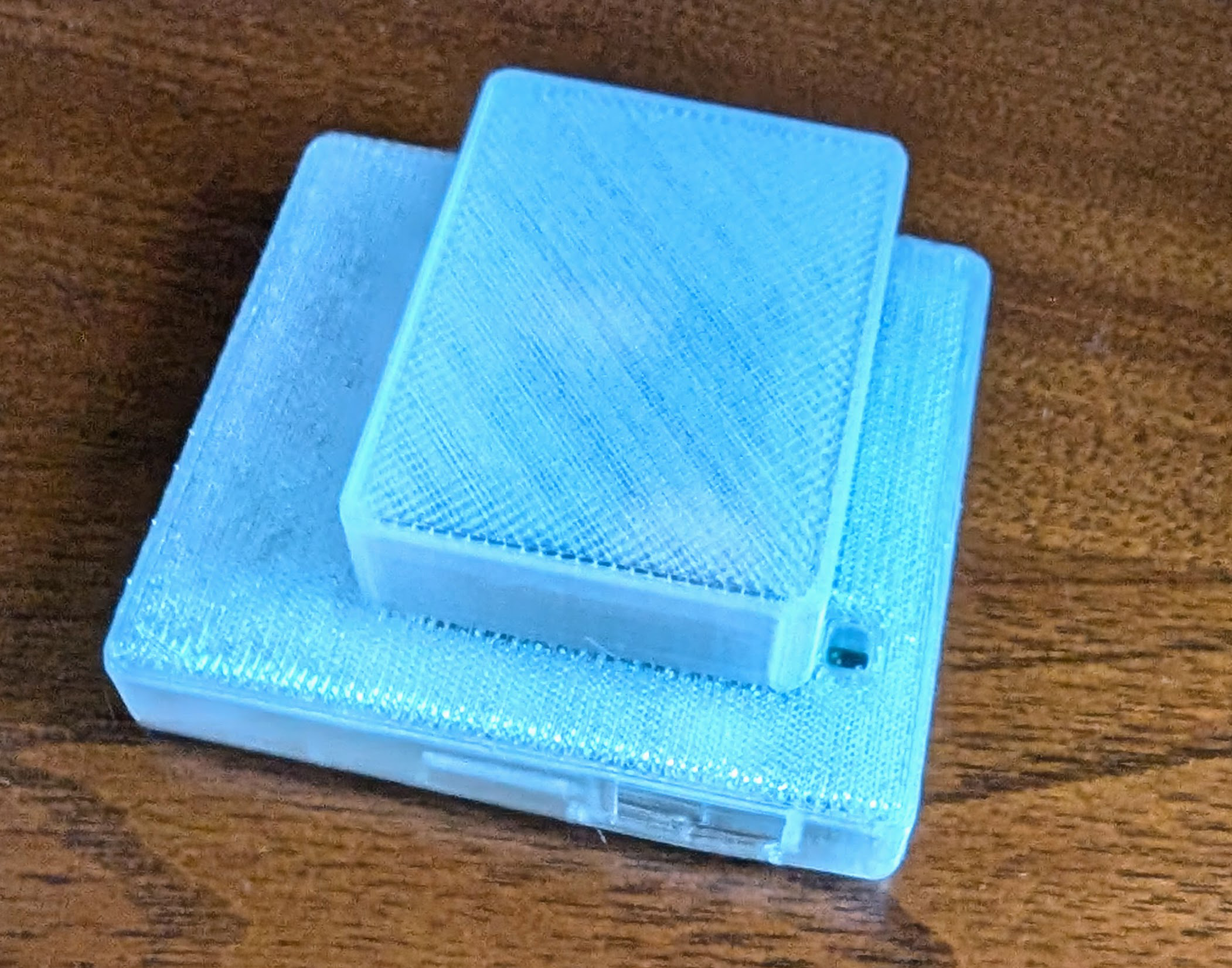
Vitamins
When designing a model of a functional 3D design, you typically need models of “Vitamins”, which are non-printed parts used in the design. For examples, see “Designing 3D Printable Mechanisms in OpenSCAD”, “OpenSCAD for Machine Design”, and the NopSCADlib vitamin library for OpenSCAD.
For Room133, the most important Vitamin is a model of the printed circuit board assembly
(PCBA) which the project box will contain.
The PCBA is the printed circuit board populated by electronic components and connectors.
The PCBA vitamin can be easily generated from the KiCAD2 circuit board model by using
the VRML export option.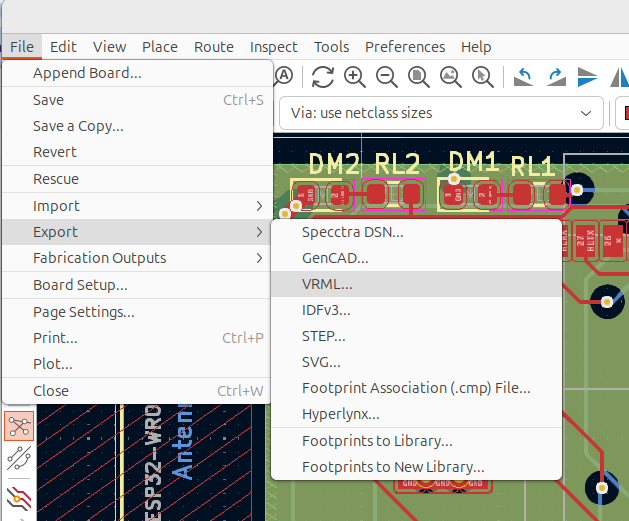
If there are parts of the device which are not included in the PCBA model, you can find a model for them online or create one yourself, then add them for the model for your board.
The ProjectBox system has a script to create a skeleton project from a template.
Running this, and editing the "board.scad" file, I came up with something like this
for the Room133 board.
Here, oled91 is a model I made for the .91" OLED display I used for some Room133 devices.
In this file and elsewhere, I use the term “EBox” to mean “electronics box”, which means
the same thing as “project box” in this context.
// mm between pads in perf-board (1/10 inch)
pad_space = 2.54;
// The size of the PCB, for use in the design of the EBox
board_thickness = 1.6;
board_dims = [18.75 * pad_space, 15.5 * pad_space, board_thickness];
// The distance of each edge of the PCB to the center of the
//  screw holes for mounting the board at each corner
mount_offset = pad_space;

// The position of the OLED screen with respect to the PCB
module room133_to_oled_frame() {
  u = pad_space;
  translate([u*8.1, 1, 12]) children();
}

// A model of the Room133 PCBA with OLED screen, for use in EBox design.
module Room133_board() {
  // Board imported from KiCad (VRML) -> MeshLab.
  translate([board_dims[0]/2, board_dims[1]/2, board_dims[2]/2]) color("white")
    import(file="RoomL33a.stl", convexity=3);
  // OLED screen
  room133_to_oled_frame() oled91();
}
The size of the board can be measured in the KiCAD layout editor.
The xy-position of the OLED pins were aligned with the header in this case simply by
iteratively editing the file while viewing the model.
The height of the screen relative to the header is determined by experience with
other projects and their boxes.
The resulting model in OpenSCAD is shown below.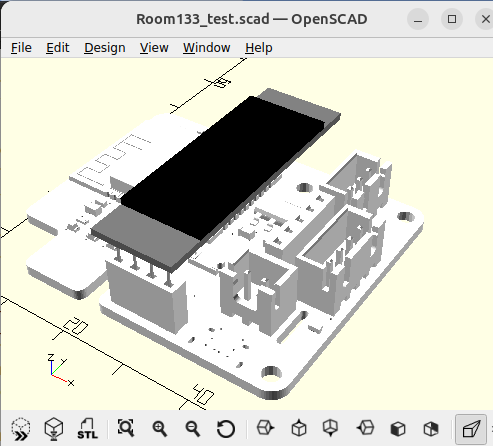
The basic box
In designing the project box, I tend to use a section of code like this to generate basic
box dimensions from the size of the board in variable board_dims.
ones = [1, 1, 1];

// The walls of the EBox are 1mm thick.
wall_thickness = 1;
// Gap distance between PCB and ebox walls.
gap = 0.2;
// Round the edges of the EBox with a 2mm radius.
corner_radius = 2;

// The basic EBox only has 2mm space above the board.
space_above_board = 2;
// This is the space below the box, used for the screw mounts.
space_below_board = 3;
// This is the space around the PCBA which the EBox should not intersect.
inner_dims = (board_dims
	      + Z*(space_above_board+space_below_board)
	      + 2*gap*ones);
// This is the size of the outer-surface of the EBox.
outer_dims = (inner_dims
	      + 2*ones*wall_thickness
	      + [2, 2, 0] * corner_radius);
The dimensions space_below_board and space_above_board control the distance between the
top and bottom of the PCB board and the bottom and top of the box.
Given this, the core of the box model is generated from the project_box module from the
ProjectBox library.
      project_box(outer_dims,
		  wall_thickness=wall_thickness,
		  gap=gap,
		  corner_radius=corner_radius,
		  top=top,
		  screw_tab_d=screw_tab_d);
The parameters are:
outer_dims: the dimensions of the outer surface of the boxwall_thickness: the width of the walls of the boxgap: extra space between surfaces which might otherwise touchcorner_radius: how much to round the x/y (horizontal) edges of the boxtop: whether to generate the top or bottom part of the boxscrew_tab_d: if nonzero, the radius of a screw-hole for a mounting-tab to add to on the outside of the box.
On the bottom part of the box, I tend to add mounts which the PCB can be screwed-into
via mounting holes at the corners of the board.
For these I generally use m2.5 screws.
I add these with the screw_mount module in the ProjectBox library:
if (!top) {
    in_Room133_board_frame() at_corners(board_dims, mount_offset)
        screw_mount(space_below_board, wall, 2.5/2);
}
This is the bottom part of the resulting box, which the board can be secured
into with a couple screws.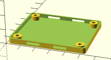
One feature to note is that there are holes into which tabs on the top of the box can
be snapped.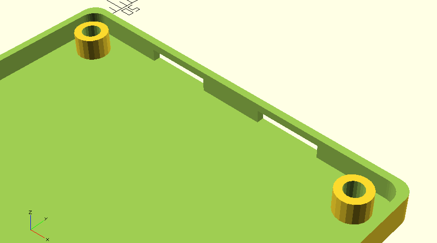
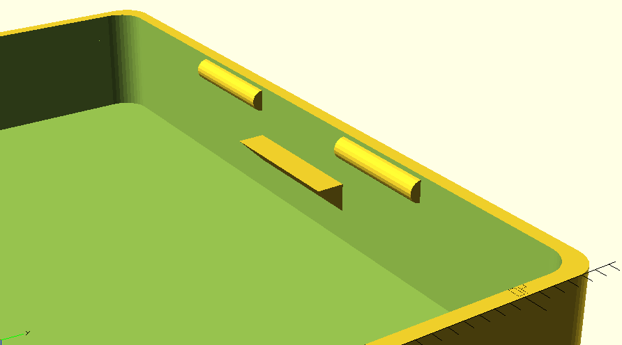
This is how the box bottom looks when the board vitamin is added: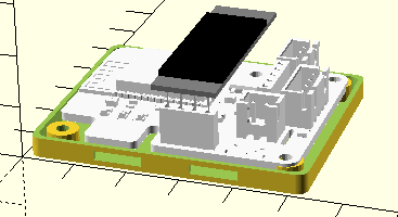
This is a photo of the “real thing”, with the board configured for use as a water-level
monitor for my boiler.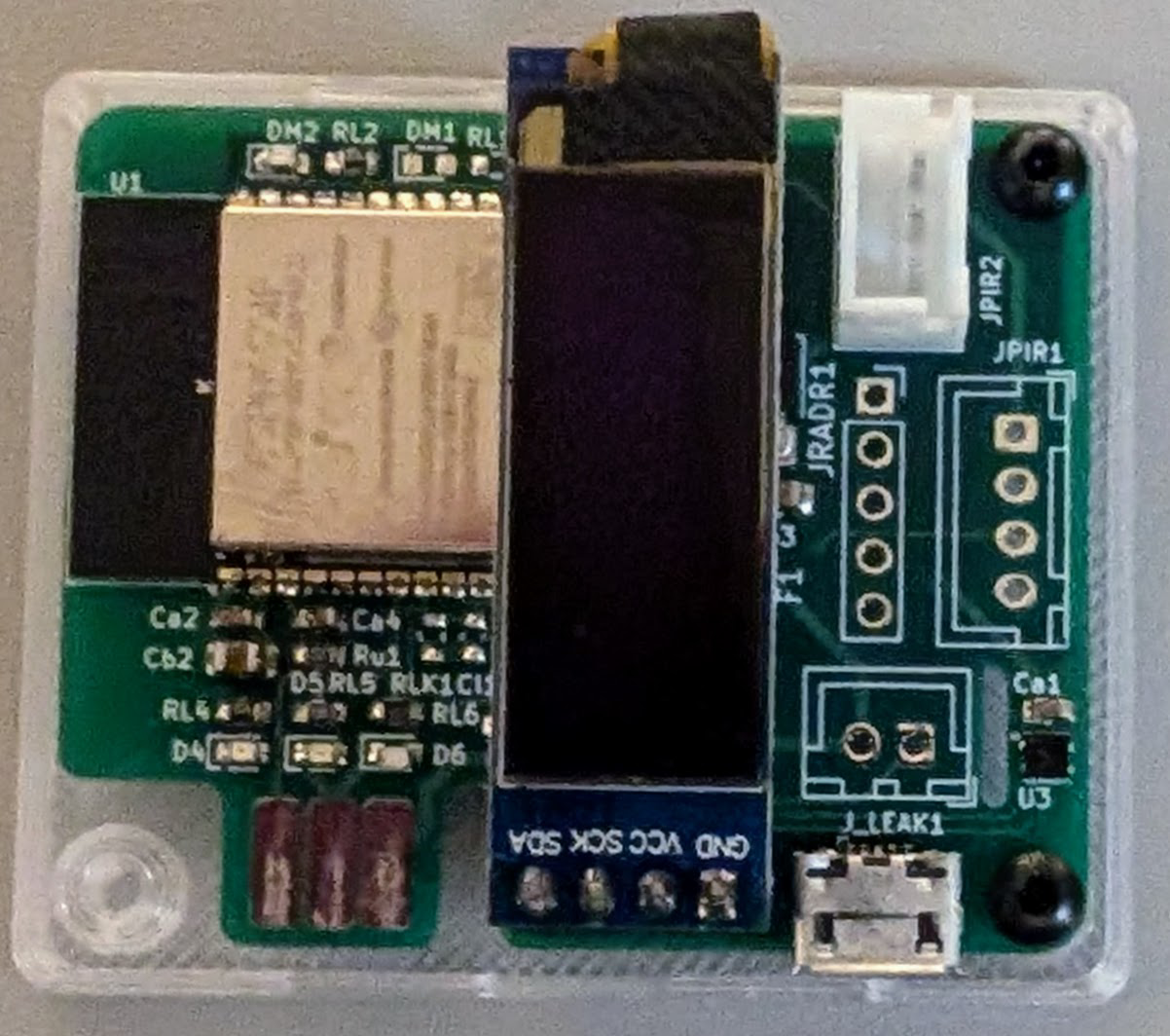
Configuration GUI
I wrote a simple Python GUI to quickly update my model and its view when building an
EBox design in OpenSCAD.
This GUI is part of the code automatically generated from the project template.
It reads a "gui.scad" file with a set of drawing options, which is referenced using
include <> in the box and board files.
The GUI window automatically adds buttons for the options marked with the special
:GUI: comment.
This comment can be specialized to generate widgets for numerical values.
For Room133, these options are used:
- To allow rapid switching between viewing the top and bottom of the box,
- To toggle display of the box and of the vitamins, and
- To set configuration options for the box and board model, such as support for the OLED screen, radar, and different connectors.
These options are used in if statements in the code which generates the box.
When you press the buttons in the GUI, the "gui.scad" file is immediately rewritten with
updated values, and the OpenSCAD window automatically redraws its model with the updated
configuration.
The Room133 project includes the following OpenSCAD file "gui.scad".
// :GUI:
leak_check = true;
// :GUI:
oled = false;
// :GUI:
mount_tab = false;
// :GUI:
motion_light = true;
// :GUI:
motion = true;
// :GUI:
radar = false;
// :GUI:
show_vitamins = true;
// :GUI:
show_box = true;
// :GUI:
top = true;
This is the resulting GUI window for specializing the box and configuring it for a given
device.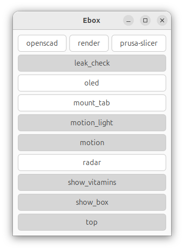
Here is the basic shape for the top of the EBox, with an added hole for the USB power
connector and a feature for exposing the SHTC3 sensor to the ambient air while shielding
it from the air in the rest of the EBox.
This is the box top generated when no connectors are selected, and no OLED screen or radar
are selected.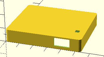
Cutouts
To make holes for connectors and other things which need to protrude
past the surface of the box, I subtract cubes from the basic project box
using the OpenSCAD difference operation.
If we add the vitamins with all potential connectors populated, this can be used as a
guide for making these cut-outs.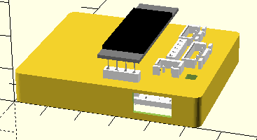
Bumps
In the picture above, the OLED screen is fully outside the basic box. So when we include an OLED screen with a device, we need extra volume to enclose it. We also want easy access to the connectors, however, so in their vicinity it is best to keep the top of the box near the board. For things like this, we can add extra “bumps” to the model.
Here we added options for a bump and cutout for the OLED screen and, a cutout for the “PIRL”
connector.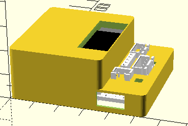
project_box module has some new code to automate the addition of these bumps.
Printing and supports
The bottom of the box can almost always be printed without supports. Supports are additional printed material underneath parts of the desired shape which cannot otherwise be printed . The support material is designed to be broken-off from the desired part after printing is completed.
In many cases, the top of the box can also be printed without supports.
However, the use of bumps in box design tends to necessitate supports.
In the 3D print plan below from PrusaSlicer, the light green material is the support which
enables printing the part of the box above.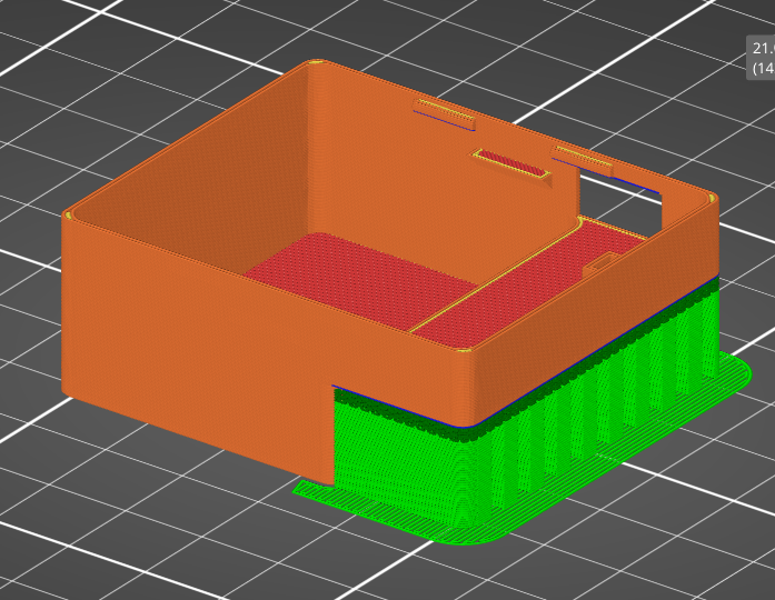
Room133 box configurations
This is a quick gallery of box configurations used for different Room133 devices.
OLED and PIRL
This for the case with an OLED screen, and a connector for passive infrared motion detector
combined with a photoresistor to measure light level.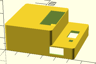
OLED, PIR, and leak detector
This is a similar box, but with a PIR sensor (and no photodiode) along with a connector
for a leak detector.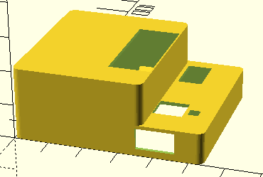
Radar
If we select the option for the radar-based presence sensor this is the resulting box.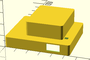
References
OpenSCAD is an open source program implementing a programming language for building 3D models. It is a way to build models using solid modeling primitives. ↩︎
MeshLab is an open source system for processing and editing 3D triangular meshes. ↩︎
PrusaSlicer ( GitHub project) is an open source G-code generated for 3D printers. ↩︎
Home Assistant is a popular Open Source home automation platform. It is the hub for my own smart home, and it is fun to work with. ↩︎